CONTROL AND REGULATION OF THE LS DIFFERENTIAL
PRESSURE AND ADJUSTMENT OF THE LS VALVE
20-43
TESTING AND ADJUSTMENTS
CONTROL AND REGULATION OF THE LS DIFFERENTIAL
PRESSURE AND ADJUSTMENT OF THE LS VALVE
Test
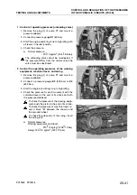
1. Test method with differential pressure gauge E3
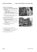
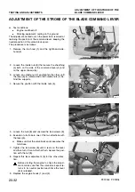
1 - Remove the plugs (1) and (2) and mount two pres-
sure adapters.
2 - Connect the differential pressure gauge
E4
.
H
Connect the high-pressure side to the adapter
(3) and the low-pressure side to the adapter
(4).
3 - Start the engine and use the working equipment
to raise one track-shoe.
4 - Bring the engine up to high idling and check the
LS differential pressure according to the test con-
ditions in Table 1.
Table 1
Position of
the travel
lever
LS differential pressu-
re in kg/cm
2
NOTES
Neutral
20 10
The LS differential pressure
is equal to the pressure gi-
ven by the unloading valve
Half the
stroke (Swing
without load)
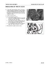
2. Test method with pressure gauges E2 or E3
H
The maximum differential pressure is 20 kg/cm
2
(roughly 20 bar). For a precise check use the sa-
me pressure gauge together with a decimal scale.
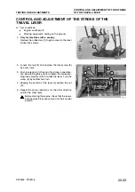
1 - Remove the plugs (1) and (2) and mount two
pressure adapters.
2 - Connect pressure gauge
E2
or
E3
to the pressu-
re adapter (3).
3 - Start the engine and use the working equipment
to raise one track-shoe.
4 - Bring the engine up to high idling and measure
the delivery pressure of pump (
P
P
) in the condi-
tions shown in Table 1. Make a note of the values
read.
H
Check the instrument by reading it from the
front and making sure that the reading is cor-
rect.
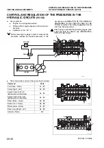
5 - Disconnect the pressure gauge
E2
or
E3
from the
pump delivery and connect it to the pressure
adapter (4).
6 - Measure the
LS
pressure in the same conditions
indicated at point 4. Make a note of the value read.
7 - Subtract the
LS
pressure from the delivery pres-
sure of the pump (
P
P
) in order to obtain the diffe-
rential pressure value
D
P
LS
(
P
P
±
LS
=
D
P
LS
)
H
D
P
LS
normal=20 10 kg/cm
2
(19.6 9.8 bar)
PC12R-8 PC15R-8
RKPA0330
2
1
RKPA2040
4
3
E
4
RKPA0321
2
3
E
3
RKPA0340
4
1
E
3
Summary of Contents for PC12R-8 MISTRAL
Page 1: ......
Page 2: ...40 28 PC15R 8 ...
Page 4: ...00 2 PC12R 8 PC15R 8 ...
Page 17: ...GROUP 10 ...
Page 18: ...40 28 PC15R 8 ...
Page 30: ...10 12 PC12R 8 PC15R 8 PAGE INTENTIONALLY LEFT BLANK ...
Page 32: ...10 14 PC12R 8 PC15R 8 PAGE INTENTIONALLY LEFT BLANK ...
Page 34: ...10 16 PC12R 8 PC15R 8 PAGE INTENTIONALLY LEFT BLANK ...
Page 36: ...10 18 PC12R 8 PC15R 8 PAGE INTENTIONALLY LEFT BLANK ...
Page 38: ...10 20 PC12R 8 PC15R 8 PAGE INTENTIONALLY LEFT BLANK ...
Page 40: ...10 22 PC12R 8 PC15R 8 PAGE INTENTIONALLY LEFT BLANK ...
Page 42: ...10 24 PC12R 8 PC15R 8 PAGE INTENTIONALLY LEFT BLANK ...
Page 44: ...10 26 PC12R 8 PC15R 8 PAGE INTENTIONALLY LEFT BLANK ...
Page 79: ...10 61 PC12R 8 PC15R 8 PAGE INTENTIONALLY LEFT BLANK ...
Page 130: ...10 112 PC12R 8 PC15R 8 PAGE INTENTIONALLY LEFT BLANK ...
Page 132: ......
Page 133: ...GROUP 20 ...
Page 134: ...40 28 PC15R 8 ...
Page 158: ...20 24 PC12R 8 PC15R 8 PAGE INTENTIONALLY LEFT BLANK ...
Page 198: ......
Page 199: ...GROUP 30 ...
Page 200: ...40 28 PC15R 8 ...
Page 283: ...GROUP 40 ...
Page 284: ...40 28 PC15R 8 ...
Page 317: ...40 33 PC12R 8 PC15R 8 PAGE INTENTIONALLY LEFT BLANK ...
Page 324: ......


