SECTION 3 - CHASSIS, PLATFORM, & SCISSOR ARMS
31215923
3-19
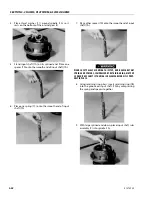
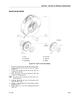
7. With the large end down, place the disconnect cap
(6D) onto the cover cap (6B), aligning the pipe plug
hole in the disconnect cap over the pipe plug hole in
the cover cap.
8. Place the two remaining bolts (6C) into the bolt holes
in the disconnect cap (6D), and tighten the bolts.
9. Using a torque wrench, apply 2.95 to 3.69 ft. lbs. (4 to
5 Nm) of torque to both bolts (6C).
10. Apply a light coat of "Never-Seize" to pipe plug (6H)
and tighten it into the pipe plug hole in the cover
(6A).
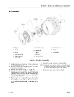
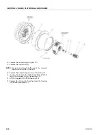
Hub-Spindle Sub-Assembly
NOTE:
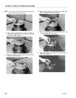
Make sure the cup sits square with the counterbore
before pressing.
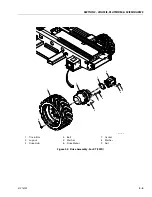
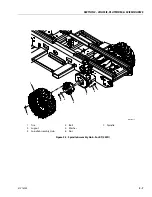
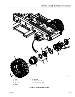
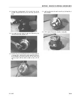
1. Set hub (1G) onto its large end. Press bearing cup
(1C) into the counterbore in the small end of the hub
(1G).
2. Press the nine studs (1N) into the stud holes in hub
(1G).
Summary of Contents for ERT2669
Page 2: ......
Page 4: ...INTRODUCTION A 2 31215923 REVISON LOG Original Issue A January 08 2021...
Page 12: ...viii 31215923 TABLE OF CONTENTS...
Page 40: ...SECTION 1 SPECIFICATIONS 1 22 31215923...
Page 58: ...SECTION 2 GENERAL 2 18 31215923...
Page 187: ...SECTION 4 BASIC HYDRAULIC INFORMATION SCHEMATICS 31215923 4 11...
Page 206: ...SECTION 4 BASIC HYDRAULIC INFORMATION SCHEMATICS 4 30 31215923...
Page 225: ...SECTION 4 BASIC HYDRAULIC INFORMATION SCHEMATICS 31215923 4 49...
Page 242: ...SECTION 4 BASIC HYDRAULIC INFORMATION SCHEMATICS 4 66 31215923...
Page 307: ...SECTION 5 JLG CONTROL SYSTEM 31215923 5 65...
Page 334: ...SECTION 6 LSS SETUP CALIBRATION SERVICE 6 12 31215923...
Page 362: ...SECTION 7 GENERAL ELECTRICAL INFORMATION SCHEMATICS 7 28 31215923...
Page 374: ...SECTION 7 GENERAL ELECTRICAL INFORMATION SCHEMATICS 7 40 31215923...
Page 375: ......

