SECTION 5 - JLG CONTROL SYSTEM
31215923
5-1
SECTION 5. JLG CONTROL SYSTEM
5.1
ANALYZER
Connecting the Analyzer
1. Connect the four pin end of the cable supplied with
the Analyzer to the four position connector on the
the analyzer connector (
1
). Connect the remaining
end of the cable to the analyzer.
NOTE:
The cable has a four pin connector at each end. It
cannot be connected backwards.
2. Power up the control system by turning the lower
key to the platform position and pulling out both
emergency stop buttons.
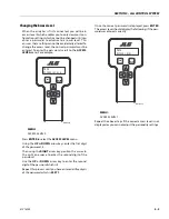
MENU:
HELP:PRESS ENTER
Analyzer Display
Escape Key
To return home or
access previous menu
Enter Key
Stores and selects Top Level,
Sub Level, and item menus
Left & Right Arrow Keys
Used to move between Top
Level, Sub Level, and item
Up & Down Arrow Keys
Value Selector
1. Analyzer Connector
MAF42750
1
Summary of Contents for ERT2669
Page 2: ......
Page 4: ...INTRODUCTION A 2 31215923 REVISON LOG Original Issue A January 08 2021...
Page 12: ...viii 31215923 TABLE OF CONTENTS...
Page 40: ...SECTION 1 SPECIFICATIONS 1 22 31215923...
Page 58: ...SECTION 2 GENERAL 2 18 31215923...
Page 187: ...SECTION 4 BASIC HYDRAULIC INFORMATION SCHEMATICS 31215923 4 11...
Page 206: ...SECTION 4 BASIC HYDRAULIC INFORMATION SCHEMATICS 4 30 31215923...
Page 225: ...SECTION 4 BASIC HYDRAULIC INFORMATION SCHEMATICS 31215923 4 49...
Page 242: ...SECTION 4 BASIC HYDRAULIC INFORMATION SCHEMATICS 4 66 31215923...
Page 307: ...SECTION 5 JLG CONTROL SYSTEM 31215923 5 65...
Page 334: ...SECTION 6 LSS SETUP CALIBRATION SERVICE 6 12 31215923...
Page 362: ...SECTION 7 GENERAL ELECTRICAL INFORMATION SCHEMATICS 7 28 31215923...
Page 374: ...SECTION 7 GENERAL ELECTRICAL INFORMATION SCHEMATICS 7 40 31215923...
Page 375: ......


