background image

SECTION 3 - CHASSIS, PLATFORM, & SCISSOR ARMS

31215923

3-73

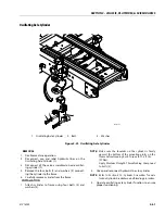
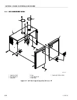
1.

Engine Cover Shield

2.

Door Compartment

3.

Locking Latch

4.

Hinge

5.

Latch Striker Bracket

6.

Hood Bumper

Figure 3-52.  Left Side - Battery Compartment Covers - ERT

MAF43870E

2

2

5

4

1

6

6

3

Summary of Contents for ERT2669

Page 1: ...Service and Maintenance Manual Models RT2669 RT3669 ERT2669 ERT3669 PVC 2004 31215923 January 08 2021 Rev A AS NZS...

Page 2: ......

Page 3: ...fort should be made to relieve any system pressure prior to disconnecting or removing any por tion of the system Relieve system pressure by cycling the applicable con trol several times with the engin...

Page 4: ...INTRODUCTION A 2 31215923 REVISON LOG Original Issue A January 08 2021...

Page 5: ...l Data 1 2 Fluid Capacities For RT 1 2 Fluid Capacities For ERT 1 2 Drive Information 1 2 Steering Information 1 2 Batteries For ERT 1 3 Tires 1 3 Critical Stability Weights 1 3 1 2 Serial Number Loca...

Page 6: ...Bearings 2 9 Gaskets 2 9 Bolt Usage and Torque Application 2 9 Hydraulic Lines and Electrical Wiring 2 10 Hydraulic System 2 10 Lubrication 2 10 Battery 2 10 Lubrication and Servicing 2 10 2 4 Lubric...

Page 7: ...r Sub Assembly 3 18 Hub Spindle Sub Assembly 3 19 Main Assembly 3 21 Tool List 3 26 Re Aligning Torque Hub Input Coupling 3 26 3 4 Drive Hub 4WD FOR RT 3 27 3 5 Drive Hub For ERT 3 28 Tightening and T...

Page 8: ...3 75 Ground Control Station Components 3 77 3 14 Battery 3 79 3 15 Tank 3 81 Removal 3 81 Installation 3 81 3 16 Battery Charger 3 83 Delta Q Battery Charger 3 83 Battery Charging 3 83 Battery Charge...

Page 9: ...lating Axle Test Non CE Market Only 4 3 4 5 Gear Pump Priming 4 4 4 6 Hydraulic Component Start Up Procedures Recommendations 4 4 4 7 Hydraulic Valves 4 6 Main Hydraulic Valve 4 8 Junction Manifold Va...

Page 10: ...Oscillating Axle Tilt Sensor CE or Quiklevel Equipped Machines Only 5 68 Elevation Sensor 5 68 Rear Axle Tilt Sensor Quiklevel Equipped Machines Only 5 69 Joystick 5 70 Steer Sensor ERT Family Only 5...

Page 11: ...nections 7 4 7 4 Dielectric Grease Application 7 5 AMP Mate N Lok 7 5 AMP Faston 7 5 AMP Micro Fit 7 5 AMP Mini Fit Jr 7 5 Mini Fit Sr 7 6 DIN Connectors 7 6 Exceptions 7 6 7 5 AMP Connector 7 7 Assem...

Page 12: ...viii 31215923 TABLE OF CONTENTS...

Page 13: ...3 3 11 Hub Spindle Disassembly 3 34 3 12 Cover Disassembly 3 35 3 13 Drive Hub Cross Section For ERT 3 39 3 14 Drive Motor Cross Section 3 40 3 15 Removing the Shaft Seal 3 40 3 16 Loop Flushing Spool...

Page 14: ...Electrical Component Locations For RT 3 110 3 74 Duel Fuel Engine Compartment Electrical Component Locations For RT 3 111 3 75 Duel Fuel Engine Compartment Electrical Component Locations For RT 3 112...

Page 15: ...t 1 of 6 4 60 4 48 Hydraulic Schematics For ERT Sheet 2 of 6 4 61 4 49 Hydraulic Schematics For ERT Sheet 3 of 6 4 62 4 50 Hydraulic Schematics For ERT Sheet 4 of 6 4 63 4 51 Hydraulic Schematics For...

Page 16: ...For RT Sheet 7 of 13 7 21 7 25 Electrical Schematic For RT Sheet 8 of 13 7 22 7 26 Electrical Schematic For RT Sheet 9 of 13 7 23 7 27 Electrical Schematic For RT Sheet 10 of 13 7 24 7 28 Electrical...

Page 17: ...91 3 16 AC Generator Specifications 3 98 4 1 Main Valve Port Identification For RT 4 9 4 2 Main Valve Torque Specs All Specs Except CE For RT 4 9 4 3 Main Valve Porting Specs For RT 4 9 4 4 Junction...

Page 18: ...rformance 6 8 6 6 LSS Troubleshooting Chart Host System Functionality 6 9 6 7 LSS Module System Interface Connector Power Digital J1 Grey 6 10 6 8 LSS Module System Interface Connector Communication J...

Page 19: ...6psi 150bar ElectricalSystemVoltage 12V InsideTurningRadius 83in 2 1m OutsideTurningRadius 174 8in 4 4m GrossVehicleWeight SingleOscillatingAxle 8090 8240lb 3670 3737kg 9080 9230lb 4118 62 4186 65 kg...

Page 20: ...rmStowed 9 5in 24 13cm 9 5in 24 13cm MachineHeight TopofRails PlatformStowed 96 6in 245 36cm 102 8in 261 11 cm MachineWidth 69 25in 175 89 cm 69 25in 175 89 cm MachineLength 138 9in 352 8cm 138 9in 35...

Page 21: ...e front Specification Lead Acid Voltage Total PerBattery 48V 6V 48V 6V AmpHourRating 310Amp 20hr 225Amp 20hr ReserveCapacity 675minutes 447minutes Size Ply Rating Foam Fill Tire Assembly Rating Wheel...

Page 22: ...inimumdrippingpoint of350 F Excellentwaterresistanceandadhesivequalities andbeingofextremepressuretype TimkenOK40pounds minimum EPGL ExtremePressureGearLube oil MeetingAPIserviceclas sificationGL 5orM...

Page 23: ...Optional MOBIL UNIVIS HVI 26 UNSHEARED SHEARED UNSHEARED SHEARED ISOViscosityGrade 32 26 SpecificGravity 0 866 0 89 PourPoint 76 F 60 C 76 F 60 C FlashPoint 212 F 100 C 201 2 F 94 C BaseOilType HV HV...

Page 24: ...5 576 5mm 1 96in 50mm RAMLockoutCylinder OscillatingAxle 3 02in 76 78mm 3 26in 83mm 3in 75mm SteerCylinder 2 5in 63 5mm 9 13 9 37in 232 238mm 1 25in 31 8mm Emissions CARB EPA Tier4Final ChinaStage III...

Page 25: ...22 8kw 3500rpm LP 26 7Hp 19 9kw 3500rpm GrossTorque Gasoline 49 1ft lbs 66 6Nm 2400rpm LP 48 8ft lbs 66 2Nm 1800rpm Description Specification BatteryCharger Delta Q ElectricalSystemVoltage DC 48V 960W...

Page 26: ...and Alarm A red warning light on the control panel illuminates and an audible alarm sounds when the chassis is at or beyond the tilt cutout settings IF THE TILT INDICATOR WARNING LIGHT ALARM IS ACTIV...

Page 27: ...E RANGE CONSULT JLG SERVICE OPERATION IN THIS TEMPERATURE RANGE SHOULD INCLUDE THE USE OF HYDRAULIC SYSYEM HEATING AIDS CONSULT JLG SERVICE 1001256522 A MAF42060A Figure 1 3 Hydraulic Oil Operating Te...

Page 28: ...PACKAGE RECOMMENDED JLG ARTIC PACKAGE SAE10W 30 or SAE10 SAE10W 30 or SAE20 SAE10W 30 or SAE30 MAF05460A Figure 1 4 Engine Oil Operating Temperature Specifications Kubota Dual Fuel Engine For RT 10011...

Page 29: ...of Loctite 242 Vibra TITE 122 can be substituted in place of Vibra TITE 121 JLG PN Loctite ND Industries Description 0100011 242 Vibra TITE 121 MediumStrength Blue 1001095650 243 Vibra TITE 122 Mediu...

Page 30: ...102 55 75 85 116 68 92 20 0 5000 0 1599 10700 90 122 65 88 100 136 80 108 9 16 12 0 5625 0 1820 11600 110 149 80 108 120 163 98 133 18 0 5625 0 2030 12950 120 163 90 122 135 184 109 148 5 8 11 0 6250...

Page 31: ...130 80 110 20 0 5000 0 1599 14400 120 165 110 150 90 120 9 16 12 0 5625 0 1820 16400 155 210 140 190 115 155 18 0 5625 0 2030 18250 170 230 155 210 130 175 5 8 11 0 6250 0 2260 20350 210 285 190 260 1...

Page 32: ...3 0 5000 0 1419 9050 65 90 60 82 55 75 20 0 5000 0 1599 10700 75 100 71 97 65 88 9 16 12 0 5625 0 1820 11600 90 120 87 118 80 109 18 0 5625 0 2030 12950 105 145 97 132 90 122 5 8 11 0 6250 0 2260 1440...

Page 33: ...80 110 20 0 5000 0 1599 14400 100 135 95 130 90 120 9 16 12 0 5625 0 1820 16400 130 175 125 170 115 155 18 0 5625 0 2030 18250 145 195 135 185 130 175 5 8 11 0 6250 0 2260 20350 180 245 170 230 160 22...

Page 34: ...18 0 5625 0 2030 18250 145 195 135 185 130 175 5 8 11 0 6250 0 2260 20350 180 245 170 230 160 220 18 0 6250 0 2560 23000 205 280 190 260 180 245 3 4 10 0 7500 0 3340 30100 320 435 300 415 280 380 16 0...

Page 35: ...55 18 0 5625 0 2030 18250 145 195 135 185 130 175 5 8 11 0 6250 0 2260 20350 180 245 170 230 160 220 18 0 6250 0 2560 23000 205 280 190 260 180 245 3 4 10 0 7500 0 3340 30100 320 435 300 415 280 380 1...

Page 36: ...10 1 5 58 00 25 2 50 38 45 55 12 1 75 84 30 36 7 88 66 79 97 14 2 115 50 0 140 105 126 154 16 2 157 68 3 219 164 197 241 18 2 5 192 83 5 301 226 271 331 20 2 5 245 106 5 426 320 383 469 22 2 5 303 13...

Page 37: ...37 33 27 10 1 5 58 00 36 1 70 65 55 12 1 75 84 30 52 5 125 115 95 14 2 115 71 6 200 180 150 16 2 157 97 8 315 280 235 18 2 5 192 119 5 430 385 325 20 2 5 245 152 5 610 550 460 22 2 5 303 189 0 830 75...

Page 38: ...5 36 60 15 9 22 20 19 10 1 5 58 00 25 2 43 40 38 12 1 75 84 30 36 7 75 70 66 14 2 115 50 0 119 110 105 16 2 157 68 3 186 175 165 18 2 5 192 83 5 256 240 225 20 2 5 245 106 5 362 340 320 22 2 5 303 132...

Page 39: ...22 8 31 29 27 10 1 5 58 00 36 1 61 58 55 12 1 75 84 30 52 5 105 100 95 14 2 115 71 6 170 160 150 16 2 157 97 8 265 250 235 18 2 5 192 119 5 365 345 325 20 2 5 245 152 5 520 490 460 22 2 5 303 189 0 7...

Page 40: ...SECTION 1 SPECIFICATIONS 1 22 31215923...

Page 41: ...spection shall be accomplished for each machine in service for 3 months or 150 hours which ever comes first out of service for a period of more than 3 months or when purchased used The frequency of th...

Page 42: ...pection is over due Maintenance and Inspection Schedule Codes 1 Check for proper and secure installation adjust ment or torque 2 Visual inspection for damage cracks corrosion abrasions distortion exce...

Page 43: ...l offwhenreleased 1 3 1 3 LoadSensingSystem 32 3 9 2 PLATFORMASSEMBLY Platform 1 1 Mandrillchain gate barandlatches 1 3 1 3 ExtenddeckandLocks 1 3 1 3 GuardrailsandFloor 1 2 1 2 Platformrollpinsandfol...

Page 44: ...1 3 4 5 1 3 4 5 NOTE Refer to Engine Operators Manual for Engine Specific instructions HYDRAULIC ELECTRICSYSTEM HydraulicCylinders 2 4 5 2 4 5 Pumps OillinesandReservoir 1 2 4 1 2 4 HydraulicFilter 4...

Page 45: ...initial use of machine This only occurs once in machine life GeneralStructuralConditionandWelds 2 2 Greaseandlubricationspecification 9 9 Functiontestofallsystem 9 9 NotifyJLGchangeinmachineownership...

Page 46: ...al offwhenreleased 1 3 1 3 LoadSensingSystem 32 3 9 2 PLATFORMASSEMBLY Platform 1 1 Mandrillchain gate barandlatches 1 3 1 3 ExtenddeckandLocks 1 3 1 3 GuardrailsandFloor 1 2 1 2 Platformrollpinsandfo...

Page 47: ...cap breatherandvent 1 4 HydraulicFitting 1 4 ElectricalConnections 1 3 1 3 Switches gauges hornandlights 1 3 1 3 Switchesandcontrols 1 3 1 3 Allhydraulicpressures 3 3 HydraulicFluid 8 8 GENERAL NoUnau...

Page 48: ...5 hours every 100 hours thereafter if equipped with engine e 50 Indicates a 50 hour interval required to perform task after initial use of machine This only occurs once in machine life CapacityDecals...

Page 49: ...lessens as the angle between the supporting structure and the component becomes less than 90 6 If a part resists removal check to see whether all nuts bolts cables brackets wiring etc have been remov...

Page 50: ...owing moisture grease filings sealing components sand etc to enter when performing maintenance or by permitting the pump to cavitate due to insufficient system warm up or leaks in the pump supply suc...

Page 51: ...ck of each system before placing the machine back in service Lubrication Specifications Specified lubricants as recommended by the compo nent manufacturers are always the best choice how ever multi pu...

Page 52: ...c tank If oil is not visible add oil until oil is visible in both ADD and FULL sight windows on tank Do not overfill tank Any time the pump coupling is removed coat splines of coupling with Texaco Cod...

Page 53: ...Front Oscillating Axle 3 Spindle Assembly 4 Torque Hub Assembly 5 Manual Descent 6 Leveling Jacks Assembly 7 Safety Prop 8 Wheels andTires 9 Ladder 10 Ground Controls 11 Platform Rails Assembly 12 Li...

Page 54: ...n GL 3 Refer to Figure 1 2 Interval Check oil every 10 hours of operation change oil every 2 years or 1200 hours of operation Capacity 13 2 gal 50 l For MRT Capacity 10 6 gal 40 l For ERT Engine Coola...

Page 55: ...ws all oil to drip back to the oil pan for accurate reading Figure 2 5 Kubota Diesel D1305 E4B Lube Point s Fill Cap Spin on Element Capacity 6 04 qt 5 7 L Engine Oil Lube EO Minimum API CF Interval I...

Page 56: ...llected debris to fall out of the air cleaner Fuel Water Separator Filter Diesel Lube Point Replaceable Element Interval Filter Change every 750 hours Quality of fuel may require replacement of filter...

Page 57: ...m the joint during opera tion 2 Filament wound bearings should be replaced if any of the following is observed a Frayed or separated fibers on the liner surface b Cracked or damaged liner backing c Be...

Page 58: ...SECTION 2 GENERAL 2 18 31215923...

Page 59: ...ate this is com plete NOTE The tilt indicator shows when the machine is outside the allowable lifting operation When the machine reaches a position within level of the specific market specification th...

Page 60: ...ment of the machine may still be improved Refer to Manual Level Adjustment Trim MANUAL LEVEL ADJUSTMENT TRIM NOTE There is an override feature on the QuikLevel Advanced system that allows the operator...

Page 61: ...tires are inflated to the pressure recommended by JLG Due to size variations between tire brands both tires on the same axle should be the same Wheel Replacement The rims installed on each product mo...

Page 62: ...IS PLATFORM SCISSOR ARMS 3 4 31215923 Drive Assembly MAF41730 2 1 3 5 4 6 8 7 Figure 3 1 Drive Assembly For RT 4WD 1 Tire Rim 2 Lugnut 3 Drive Hub 4 Bolt 5 Washer 6 Drive Motor 7 Bolt 8 Washer NOTE Fr...

Page 63: ...CTION 3 CHASSIS PLATFORM SCISSOR ARMS 31215923 3 5 1 MAF41740 2 3 4 5 5 7 6 8 9 Figure 3 2 Drive Assembly For RT 2WD 1 Tire Rim 2 Lugnut 3 Drive Hub 4 Bolt 5 Washer 6 Drive Motor 7 Gasket 8 Washer 9 N...

Page 64: ...Remove the Drive Hub 3 and Drive Motor 6 from the axle by removing the 6 Bolts 4 and Washers 5 4 4 WD Drive The Drive Motor 6 can be removed from the Drive Hub 3 by removing the 4 Bolts 7 and Washers...

Page 65: ...SECTION 3 CHASSIS PLATFORM SCISSOR ARMS 31215923 3 7 Figure 3 3 Spindle Assembly Hub For RT 2WD 1 Tire 2 Lugnut 3 Spindle Assembly Hub 4 Bolt 5 Washer 6 Nut 7 Spindle MAF46270 1 3 2 5 7 6 5 4...

Page 66: ...l electri cal wiring 2 With axle raised and supported remove the Tires 1 from the spindle assembly Hub 3 by removing the 9 Lugnuts 2 3 Remove the Spindle Assembly Hub 3 from the Spin dle 7 by removing...

Page 67: ...N 3 CHASSIS PLATFORM SCISSOR ARMS 31215923 3 9 Figure 3 4 Drive Assembly For ERT 1 Tire 2 Lugnut 3 Drive Hub 4 Bolt 5 Washer 6 Electric Drive Motor 7 Adapter Motor Plate 1001247420 F MAF44210F 1 3 2 5...

Page 68: ...tric Drive Motor 6 from the axle by removing the 6 Bolts 4 and Washers 5 5 The Electric Drive Motor 6 can be removed from the Drive Hub 3 by removing hardware securing adapter motor plate 7 and tracti...

Page 69: ...t then checking for air bubbles If you detect a leak in a seal O ring or gasket replace the part immediately Tightening and Torquing Bolts If you use an air impact wrench to tighten bolts take extreme...

Page 70: ...embly A Carrier Housing B ThrustWasher C Needle Roller D Spacer E Planet Shaft F Cluster Gear G Roll Pin 4 Ring Gear 5 O Ring 6 Cover Sub Assembly A Cover B Cover Cap C Bolt D Disconnect Cap E Disconn...

Page 71: ...23 23 29 28 30 39 20 37 40 41 22 21 21 19 27 25 26 17 18 32 31 34 33 36 35 38 16 12 1A 1B 1C 1D 1J 1G 1E 1F 1H 1 1 15 2 7 7A 7D 7D 7C 7B 6 6B 9 13 8 14 3B 3F 3C 3D 3C 3B 3 3A 3E 3G 5 4 5A 6A 11 11 6C...

Page 72: ...stSpacer 6B CoverPlate 6C O Ring 6D DisconnectRod 6E DisengageCap 6F Bolt1 2 20NCx1 2 6G PipePlug 6H Rivet 6I IDPlate 7 InputShaftAssembly 7A Shaft 7B RetainingRing 7C Spring 7D ThrustSpacer 8 SunGear...

Page 73: ...1G BEWARE OF SHARP EDGES IN COUNTERBORE WHEN YOU REMOVE THE O RING 16 Remove O ring 5 from the counterbore in hub 1G Discard the O ring 17 At this point the main disassembly for drive hub is complete...

Page 74: ...e to the carrier when removing the planet shaft from the car rier 2 Using a punch and hammer drive the planet shaft 3E out of the planet shaft hole in the carrier housing 3A 3 When removing the planet...

Page 75: ...ing the thrust washer place the cluster gear 3F large end toward roll pin hole in carrier housing onto the planet shaft 3E 7 Following the cluster gear place one more thrust washer 3B onto planet shaf...

Page 76: ...lange of the cover cap 3 Insert disconnect rod 6E into cover cap 6B 4 Set cover 6A on table exterior side up Place cover cap 6B onto cover 6A aligning the pipe plug hole in the cover cap over the pipe...

Page 77: ...nnect cap 6D and tighten the bolts 9 Using a torque wrench apply 2 95 to 3 69 ft lbs 4 to 5 Nm of torque to both bolts 6C 10 Apply a light coat of Never Seize to pipe plug 6H and tighten it into the p...

Page 78: ...the counterbore before pressing 4 Turn hub 1G over onto its small end Press bearing cup 1E down into the counterbore in the deep end of the hub 1G 5 Set hub 1G onto its large end Place bearing cone 1D...

Page 79: ...ub assembly is com plete Main Assembly BEWARE OF SHARP EDGES IN COUNTERBORE WHEN INSTALLING THE O RING 1 Grease O ring 5 and place it into the counterbore in hub 1G NOTE O ring may be stretched or pin...

Page 80: ...end of input shaft 7A 7 Place other spacer 7D onto the smooth end of input shaft 7A WEAR SAFETY GLASSES DURING THIS STEP AND BE AWARE THAT SPRING AND SPACERS COMPRESSED BY RETAINING RING MAY POP SUDDE...

Page 81: ...in the ring gear 4 over one of the shoulder bolt holes in the hub Mark the location of shoulder bolt holes on the outside of ring gear and hub NOTE You may lift the ring gear off the hub to align the...

Page 82: ...the pipe plug holes according to the align ment prior to disassembly 18 Place four flatwashers 16 on top of the bolt holes in the cover sub assembly 6 19 Place shoulder bolts 13 into the four shoulde...

Page 83: ...Insert coupling 14 into the end of the spindle 1A 24 Roll test the unit in both clockwise and counterclock wise directions Perform the same number of turns in each direction as the ratio of the unit T...

Page 84: ...re applies to torque hubs with integral brakes EQUIPMENT REQUIRED 1 Hydraulic power supply hand pump capable of pro ducing 200 psi 13 8 bar 2 Hydraulic fittings to adapt hydraulic supply to brake rele...

Page 85: ...SECTION 3 CHASSIS PLATFORM SCISSOR ARMS 31215923 3 27 3 4 DRIVE HUB 4WD FOR RT NOTE Service information not available at the time of publishing...

Page 86: ...lowing steps describe how to tighten and torque bolts or socket head capscrews in a bolt circle 1 Tighten but do not torque bolt A until snug 2 Go to the opposite side of the bolt circle and tighten b...

Page 87: ...emove the cover sub assembly 6 from the unit To remove the cover out of the unit the unit needs to be carefully pressurized with air Washer 2 may have to be removed separately due to the loose attach...

Page 88: ...and input shaft need to be removed together on units with a ration 48 1 10 Remove the output stage carrier sub assembly 4 11 Loosen and remove the 3 flat head bolts 19 that retain the ring gear 1F to...

Page 89: ...roll pin 4G out of the planet shaft 4E using a 1 8 diameter punch NOTE The roll pins 4G should not be reused when reas sembling the unit 4 Slide the planet gear sub assembly 4 out of the out put carr...

Page 90: ...23 5 Remove 4 Thrust Washers 4B 28 Needle Rollers 4C and the Thrust Spacer 4D from the Second Stage Planet Gear 4F 6 Repeat steps 1 to 5 for the remaining two Planet Gears 4F 7 Remove the Thrust Washe...

Page 91: ...rive the roll pin 4G out of the planet shaft 3E using a 1 8 diameter punch NOTE The roll pins 4G should not be reused when reas sembling the unit 4 Slide the planet 3F and the 2 thrust washers 3B out...

Page 92: ...Lift hub 1G from spindle 1A Remove boot seal 1Q from hub 1G if applicable 6 Press 9 studs 1H out from the hub 1G Locate hub 1G on seal 1B end if necessary 7 Remove seal 1B from hub 1G NOTE The Seal 1...

Page 93: ...6B from Cover 6A 4 Pull Disengage Rod 6D out from Cover 6A 5 Remove O ring 6E from internal groove in Cover 6A using appropriate tool 6 Remove two O Ring Pipe Plugs 6F from Cover 6A NOTE For reassemb...

Page 94: ...grease may need to be applied to the Thrust Washers 3B to hold them in place while installing the planet gears Output Planet Gear Sub Assembly 1 Apply a liberal coat of grease to the bore of one Out p...

Page 95: ...The Disengage Rod can be inserted either end first 4 Grease Face of Thrust Washer 2 and place in Cover 6A making sure that tangs on washer seat into pockets in cover 5 Install O Ring Pipe Plugs 6F int...

Page 96: ...SECTION 3 CHASSIS PLATFORM SCISSOR ARMS 3 38 31215923 Tool List 1 Bearing Cup Pressing Tool 2 Seal Pressing Tool 3 Smaller Bearing Cone...

Page 97: ...Needle Bearing E Planet Shaft F Planet Gear 4 Input Carrier Sub Assembly A Output Carrier B ThrustWasher C Needle Bearing D Thrust Spacer E Planet Shaft F Planet Gear G Roll Pin H ThrustWasher 5 Exter...

Page 98: ...ternal stops The large diameter servo pis ton allows smooth acceleration and deceleration with relatively large circuit orificing Shaft Seal Replacement REMOVAL 1 Remove the snap ring 1 retaining the...

Page 99: ...remove plug 3 3 Remove O rings 4 5 and 6 4 Using pliers remove centering springs 7 8 and 9 5 Remove spring retaining washers 10 and 11 6 Remove shift spool 12 7 Remove orifice poppet 13 INSPECT THE C...

Page 100: ...reservoirand oilsupplytothepump Insufficientamountofhydraulicfluidwillnotmeetthecooling demandsofthesystem Fillthereservoirtotheproperlevel Inspecttheheatexchanger if soequipped Iftheheatexchangerfail...

Page 101: ...the speed sen sor lock nut 14 if equipped Then remove the speed sensor using a 1 2 in hex wrench Units without speed sensor have an O ring plug 15 installed in that location remove it with a 1 4 in i...

Page 102: ...rt number are stamped on its surface 16 Remove and discard the O rings 27 17 Remove the rear shaft bearing 28 from the endcap with a bearing puller The bearing may be difficult to remove with a puller...

Page 103: ...metal screw into the chuck of a slide hammer Drive the screw into the seal surface and use the slide hammer to pull the seal 21 Remove the inner snap ring 35 and the shaft bear ing assembly 22 Remove...

Page 104: ...e maintain ing pressure unwind the spiral retaining ring 51 Carefully release the pressure and remove the outer block spring washer 50 block spring 52 and inner block spring washer 53 from the cylinde...

Page 105: ...ts Table 3 7 Slipper Foot Thickness End Play Measurement L Frame K Frame SlipperFootThickness mm in 2 71 0 11 4 07 0 16 Piston SlipperEndPlay 0 15 0 006 A Table 3 8 Cylinder Block Measurements Measure...

Page 106: ...iding the surface condition meets specifications shown Measure the swashplate thickness from the journals to the running face Replace swash plate if damaged or worn beyond minimum specifica tion Repla...

Page 107: ...ng the piston head into the servo cavity in the end cap and let it stand for at least five minutes 2 After piston seal has relaxed lubricate and install servo piston into the housing bore Align the pi...

Page 108: ...rnal bearings 13 into the housing seats Use assembly grease to keep the bearings seated during assembly Ensure the locating nubs drop into the cavities in the seats If you re reusing the bearings inst...

Page 109: ...ing the swashplate Rock the shaft to align the block splines and slide the cylinder kit into place Orient the motor with the shaft pointing downward and verify the cylinder kit swashplate journal bear...

Page 110: ...terference Improper assembly of the internal components may prevent the endcap from seating properly Ensure the O rings seat properly when installing the endcap 16 Using an 8 mm internal hex wrench ti...

Page 111: ...s and fittings to the housing Refer to the drawing below for wrench sizes and installation torques 29 28 27 27 ShaftSeal 28 SealSupportWasher 29 SnapRing Figure 3 34 Shaft Seal 1 4 in 45 Nm 33 ft lbs...

Page 112: ...ure it is free of restrictions and air leaks 3 Fill the pump and motor housing with clean hydrau lic fluid Pour filtered oil directly into the upper most case drain port 4 To ensure the pump and motor...

Page 113: ...ARMS 31215923 3 55 3 7 AXLE INSTALLATION 1 Axle 2 Pivot Pin 3 Pivot Pin Bushing 4 Thrust Washer 5 Pin Keeper and Bolt 6 Wear Pad 7 Wear Pad Shims 8 Hex Head Screws Figure 3 37 Axle Installation Front...

Page 114: ...emoved shim the wear pad to achieve a maxi mum gap of 0 06 in 1 5 mm between the pad and the axle machined surface 3 For Dual Oscillating Rear Axle If removed shim the wear pad to achieve a maximum ga...

Page 115: ...9 9 8 7 7 6 6 6 5 5 5 4 3 3 3 3 1 2 2 1 1001244392 B MAF42080B 13 7 14 1 1 Bolt 2 Thrust Bearing 3 Bushing 4 Flat Head Clevis Pin 5 Cotter Pin 6 Washer 7 King Pin 8 Steer Cylinder 9 Spindle 10 Tie Ro...

Page 116: ...connect tie rod 10 from the spindle 9 by removing the cotter pin 5 and clevis pin 11 con necting cylinder rod to tie rod 10 Slide the tie rod out of the spindle 9 capture the washer 6 on bot tom of ti...

Page 117: ...King Pin 8 Steer Cylinder 9 Spindle 10 Tie Rod 11 Clevis Pin 12 Washer 13 Steering Sensor Cover 14 Rotary Angle Sensor Switch 15 Steering Pin 16 Bolt 17 Locknut 18 Washer 19 Thrust Bearing Figure 3 4...

Page 118: ...mbly prior to spindle 9 removal 2 2 Remove steering sensor cover 13 by removing hardware 3 Remove rotary angle sensor switch 14 from steering pin 15 4 Supporting tie rod remove bolt 16 washer 12 and l...

Page 119: ...Attach cylinder to frame using four bolts 2 and washers 3 NOTE Make sure the shoulder on the cylinder is firmly against the bottom of the mounting plates on the frame before torquing bolts Torque to 7...

Page 120: ...linder remove hardware securing cylinder to leveling jack wedment 2 7 Carefully remove cylinder from mount INSTALLATION 1 Follow Removal Steps in reverse NOTE Refer to Figure 4 10 Cylinder Assemblies...

Page 121: ...o cylinder and switches Remove hoses and wiring from the leveling jack tube assembly 4 Remove the bolt 2 and washer 3 securing leveling jack assembly 1 to frame Repeat for other side of the frame 5 Ca...

Page 122: ...isconnect and label all electri cal wires going to platform 4 Detach the center attach link from the platform by removing the bolt 8 locknut 9 pin keeper 10 and pin 11 5 With scissor arm assembly 2 br...

Page 123: ...remove lower extrusion housing 2 7 Remove the four screws and nuts to remove the joy stick controller 4 8 The harness can be removed from the box by remov ing the harness connector terminal nut 4 and...

Page 124: ...is YAxisOnly InputVoltage 4 9 5 1VDC CurrentConsumption 10mA 12VDC CenteredOutputVoltage 2 4 2 6VDC ReverseVoltage 3 9 4 1VDC ForwardVoltage 0 9 1 1VDC Table 3 10 Joystick Plug Loading Chart Terminal...

Page 125: ...wn Scissor Arms Removal NEVER WORK UNDER ELEVATED SCISSOR ARMS WITHOUT FIRST PROPERLY BRACING BLOCKING SCISSOR ARM ASSEMBLY NOTE Scissor arms can be removed individually or as an entire assembly ARM R...

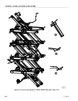
Page 126: ...ECTION 3 CHASSIS PLATFORM SCISSOR ARMS 3 68 31215923 Figure 3 47 Scissor Arm Component RT2669 ERT2669 Assembly Sheet 1 of 2 A B C C D D D D D D D D H H F F E E E E J J G A B B C MAF42040C 1001248820 C...

Page 127: ...SECTION 3 CHASSIS PLATFORM SCISSOR ARMS 31215923 3 69 D E F G H J MAF42050C 1001248820 C Figure 3 48 Scissor Arm Component RT2669 ERT2669 Assembly Sheet 2 of 2...

Page 128: ...3 CHASSIS PLATFORM SCISSOR ARMS 3 70 31215923 A B C H E E C C D D B B B B A D D D D D D D D F E E G G G G J J K F MAF42020C 1001248821 C Figure 3 49 Scissor Arm Component RT3369 ERT3369 Assembly Sheet...

Page 129: ...SECTION 3 CHASSIS PLATFORM SCISSOR ARMS 31215923 3 71 MAF42030C 1001248821 C D E F G K H J Figure 3 50 Scissor Arm Component RT3369 ERT3369 Assembly Sheet 2 of 2...

Page 130: ...23 3 12 SIDE COMPARTMENT COVERS 1 Engine Cover Shield 2 Door Compartment 3 Locking Latch 4 Hinge 5 Latch Striker Bracket 6 Hood Bumper 7 Coolant and Oil Fill Access Plate Figure 3 51 Left Side Engine...

Page 131: ...PLATFORM SCISSOR ARMS 31215923 3 73 1 Engine Cover Shield 2 Door Compartment 3 Locking Latch 4 Hinge 5 Latch Striker Bracket 6 Hood Bumper Figure 3 52 Left Side Battery Compartment Covers ERT MAF43870...

Page 132: ...CISSOR ARMS 3 74 31215923 2 2 7 4 5 1 3 MAF42160 6 6 1 Hydraulic Cover Shield 2 Door Compartment 3 Locking Latch 4 Hinge 5 Latch Striker Bracket 6 Hood Bumper 7 Hood Cover Figure 3 53 Right Side Hydra...

Page 133: ...to remove the door from the cover 6 Remove the bolts and washers from the front covers or doors remove and lay aside 7 Remove the Latch Striker Bracket by removing hard ware securing to engine or tank...

Page 134: ...and label all electrical harnesses from the ground control panel assembly 1 4 Supporting control panel assembly remove hard ware securing ground control panel assembly 1 to tank cover shield 2 5 Supp...

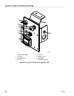
Page 135: ...Components 1 2 3 4 5 6 8 7 1001251231 C MAF42180C 1 Ground Control Panel Bracket 2 Switch Guard 3 Engine Start Push Button Switch 4 Key Switch 5 E stop Switch 6 Lift Up Down Switch 7 Ground Display 8...

Page 136: ...5923 MAF43890B 4 5 8 2 6 7 3 1 1 Ground Control Panel Bracket 2 Switch Guard 3 E Brake Release Button 4 Key Switch 5 E stop Switch 6 Lift Up Down Switch 7 Ground Display 8 LSS Overload Indicator LED F...

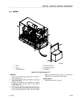
Page 137: ...2 and battery holder bracket 3 4 With the positive battery cable disconnected if nec essary the auxiliary power block 5 can be removed by first disconnecting the cables from the block Remove the bolt...

Page 138: ...orward most battery connected to the main contac tor relay 3 Remove all interconnected battery cables from the machine 4 Remove the J bolt 5 by removing hardware secur ing battery secure top plate 3 t...

Page 139: ...ation 1 Follow Removal Steps in reverse NOTE If removed before reinstalling into tank insert apply pipe sealant Medium Strength Threadlocking Com pound to fuel and vent line fittings on the fuel tank...

Page 140: ...c tank 1 to hydraulic tray 3 5 Remove hydraulic tank 1 from the hydraulic com partment INSTALLATION 1 Follow Removal Steps in reverse NOTE If removed before reinstalling into tank insert apply pipe se...

Page 141: ...arge cycle is complete when the single green LED light on the hood between the AC plug and bat tery disconnect illuminates Additionally the green LEDs on the top and bottom panels of the battery charg...

Page 142: ...SASSEMBLE CHARGER 1 For flooded lead acid batteries regularly check water levels of each battery cell after charging and add distilled water as required to level speci fied by battery manufacturer Fol...

Page 143: ...1 4in quick connectter minal normallyclosedto batterypositive Open whenthechargeroutput isactive 1 5Amax Table 3 12 IC900 IC1200 DC Output Pin Recommended Wire Size AWG mm2 Description Notes 12 4 0 I...

Page 144: ...er 2 Insert the head of the Torx T30 screwdriver into the gap on the lower right side of the DC terminal block cover and push the screwdriver in while pulling up on the cover to release the right side...

Page 145: ...d 1 Remove the DC terminal block cover by lifting it ver tically off the charger Remove the bag of parts that contains the cable clamp 2 longer Torx T10 screws and 2 shorter Torx T10 screws 2 Remove t...

Page 146: ...ide Blue 2 Interlock NC DryContactInterlockrelay Normallyclosedcontact Purple 3 Interlock Common DryContactInterlockrelay Commoncontact Pink 4 Interlock NO DryContactInterlockrelay Normallyopencontact...

Page 147: ...charging profiles The Charge Profile Error Display shows one of four possible codes to indicate different conditions F codes mean that an internal fault condition has caused charging to stop E codes m...

Page 148: ...ra bly not during a charge cycle Stop the charge cycle by removing AC power or the DC connection to the batteries The charger can power the USB port from the AC connection DC disconnected or from the...

Page 149: ...ons Replacebatterypack CheckDCconnections Disconnectparasiticloads This errorwillautomaticallyclearoncethechargerisresetbycyclingDC E 0 0 8 Batterytemperatureisoutofrange Possiblebatterytemperaturesen...

Page 150: ...eingused Ensurethe USBFlashDriveisproperlyformatted FATrecommended andretry TryadifferentUSBdrive If errorpersists contactSupport E 0 2 7 USBOverCurrentFault USBhardwareovercurrentprotectionhasbeentri...

Page 151: ...kableMessages Checktheconfigurationofallchargersthataresharingthisbus E 0 5 1 StackableCharging NoMaster Masterdevicemaybedisconnectedorpowereddown Checkwiringharness Checkconfigurationofdevices Refla...

Page 152: ...Forexamplecheckterminationresistanceisapprox 60ohms E 0 6 8 MissingCANMessagesWhileNot Charging Monitoredmessages Heartbeat PGN PDO lostwhilechargeroutputoff Checkthenetworked CANbusdevice s forcorre...

Page 153: ...lifting information 5 Remove the four large bolts nuts and washers secur ing the side engine mounting brackets 3 to the iso lator mounts 4 and engine tray 5 6 Slowly lift the engine up and out of the...

Page 154: ...moking 3 Only trained and authorized personnel are permitted to operate filling equipment 4 Fill LPG tanks outdoors Stay at least 50 ft 15 m from buildings motor vehicles electrical equipment or other...

Page 155: ...N 3 CHASSIS PLATFORM SCISSOR ARMS 31215923 3 97 Generator If Equipped 1 Generator 2 Belt 3 Generator Adjust Bracket 4 Eyebolt Rod 5 Generator Mount Figure 3 64 AC Generator Installation MAF42480B 1 4...

Page 156: ...generator 1 to gen erator mount 5 remove generator 1 9 If necessary remove generator mount 5 from the machine by removing all hardware INSTALLATION 1 Follow Removal Steps in reverse Ensure belt is tig...

Page 157: ...et access to generator pul ley remove cover 3 Loosen the hardware securing generator adjust bracket 3 to generator mount 5 Do not remove them 4 Loosen the eye bolt rod to remove the belt tension enoug...

Page 158: ...Diesel 1 Engine 2 O2 Sensor 3 Catalytic Coverter Muffler 4 Mounting Bracket 5 Gasket 6 O2 Sensor Pipe Downstream 7 O2 Sensor Pipe Upstream 1 Muffler 2 Gasket 3 Mounting Bracket Figure 3 65 Exhaust Sys...

Page 159: ...s is 28 8 36 ft lbs 39 1 48 9 Nm NOTE Use gasket and hardware supplied with engine to assemble exhaust pipe to muffler Torque to 21 7 25 3 ft lbs 29 3 34 3 Nm Diesel ALLOW ENGINE AND COMPONENTS TO COO...

Page 160: ...Gas LPG Diesel 1 Air Cleaner Assembly 2 Intake Pipe 3 Flange Bolt 4 Clamp 5 Clamp 6 90 Elbow Adapter 1 Air Cleaner Assembly 2 Intake Pipe 3 Flange Bolt 4 Clamp 5 Clamp Figure 3 66 Air Cleaner System...

Page 161: ...remove the end cap Also no need to remove the flange hard ware to remove the air cleaner assembly Loosen the clamp and slide it out Diesel ALLOW ENGINE AND COMPONENTS TO COOL DOWN BEFORE SERVIC ING R...

Page 162: ...r at the radiator mounting plate 4 Support the radiator mounting plate 1 remove hardware holding radiator assembly 2 to radiator lower support bracket 4 and radiator seal plate 5 Re check that all con...

Page 163: ...ARMS 31215923 3 105 Engine Electrical Component Locations Figure 3 68 Diesel Engine Compartment Electrical Component Locations For RT MAF41910B 1001255875 B SEE DETAIL A X88B TO CHASSIS HARNESS DETAIL...

Page 164: ...Locations For RT MAF41920B 1001255875 B SEE DETAIL D LB327 BEACON LIGHT AUX BLOCK POWER AUX BLOCK GROUND BATTERY NEGATIVE BATTERY POSITIVE SEE DETAIL B ECU SHIPPED LOOSE WITH ENGINE EC10 DIESEL ECU SE...

Page 165: ...23 3 107 Figure 3 70 Diesel Engine Compartment Electrical Component Locations For RT MAF41930B 1001255875 B RL4 GLOW PLUG RLY RL2 START RELAY RL1 IGN RELAY DETAIL C FC261 MAIN MDL FUSE FC260 ALT EXCIT...

Page 166: ...Engine Compartment Electrical Component Locations For RT MAF41940B 1001255875 B SEE DETAIL E ROUTE BAT TERY CABLE THROUGH CUTOUT ON ENGINE TRAY AS SHOWN SN5 COOLANT SNSR T6 TO ALT STUD MS150 ALT CONN...

Page 167: ...SSIS PLATFORM SCISSOR ARMS 31215923 3 109 Figure 3 72 Duel Fuel Engine Compartment Electrical Component Locations For RT 1001256034 C MAF41970C SEE DETAIL A EC10 ECM CONN X88 ENG DF CONN DETAIL A EC6...

Page 168: ...Fuel Engine Compartment Electrical Component Locations For RT MAF41980A 1001256034 A LB328 BEACON LIGHT T12 AUX BLOCK AUX BLOCK POWER BATTERY NEGATIVE AUX BLOCK GROUND BATTERY POSITIVE SEE DETAIL B D...

Page 169: ...11 Figure 3 74 Duel Fuel Engine Compartment Electrical Component Locations For RT MAF41990A 1001256034 A RL13 ETV RL RL12 PWR RL RL11 LP SELECT RL RL10 STRT RL RL1 IGN RELAY FC274 PWR RL FUSE FC273 AL...

Page 170: ...75 Duel Fuel Engine Compartment Electrical Component Locations For RT MAF42000A 1001256034 A SEE DETAIL D GD02 ENG GND DETAIL D MS156 FUEL SEL VALVE EC7 PRE O2 SNSR T6 TO ALT STUD MS153 CONN TIE DUAL...

Page 171: ...ne Compartment Electrical Component Locations For RT MAF42010A 1001256034 A ROUTE BATTERY CABLE THROUGH CUTOUT ON ENGINE TRAY AS SHOWN SEE DETAIL E SECURE THE CONNECTORS BY REUSING THE EXISTING NUT AN...

Page 172: ...ION 3 CHASSIS PLATFORM SCISSOR ARMS 3 114 31215923 MAF46990A 1001259034 A Figure 3 77 Genset Engine Compartment Electrical Component Locations For ERT SEE DETAIL A EC363B GEN POSITIVE EC363B GENERATOR...

Page 173: ...e Compartment Electrical Component Locations For ERT SEE DETAIL B CONNECT X224 TO X225 ON THE CHASSIS HARNESS INSERT MS191 3 INTO CAVITY 3 OF MS191 ON THE CHASSIS HARNESS MS191 3 GND BUS LB512 GNST DI...

Page 174: ...MAF47010A 1001259034 A Figure 3 79 Genset Engine Compartment Electrical Component Locations For ERT SEE DETAIL C SEE DETAIL D MS351 2D BATT DISCONN X637 BATT DISCONN RL462 GENST START RELAY RL463 GEN...

Page 175: ...ove the bolt and washer 3 attaching the gear pump 1 to the coupling assembly 2 Carefully remove the gear pump 1 INSTALLATION 1 Follow Removal Steps in reverse NOTE Apply Medium Strength Threadlocking...

Page 176: ...ual fuel engine remove the adapter plate 5 along with coupler housing 1 7 For Dual fuel engine remove double clamp from the coupler housing 1 8 Remove hardware securing disc coupling 2 to Engine Flywh...

Page 177: ...ition therefore when the control is released the spool auto matically returns to neutral prohibiting any flow through the circuit Relief Valves Main relief valves are installed at various points withi...

Page 178: ...airs have been made replace counterbalance valve and carefully connect hydraulic hoses to cylinder port block 6 If used remove lifting device supporting platform or release and stow safety prop activa...

Page 179: ...not function properly have qualified personnel correct the malfunction prior to any further operation Front Oscillating Axle Test Non CE Market Only NOTE Begin the test with no load in the platform i...

Page 180: ...been incurred during shipping and handling Ensure all system components reservoir hoses valves fittings heat exchanger etc are clean prior to filling with fluid Fill the reservoir with recommended hyd...

Page 181: ...TIONS TO PRE VENT MACHINE MOVEMENT IN CASE PUMP IS ACTUATED DURING INITIAL START UP Jog or slowly rotate the engine until charge pressure starts to rise Start the engine and run at the lowest pos sibl...

Page 182: ...lectrical harness connected to valves 2 Remove the valve blocks from the hydraulic tray by removing the attaching bolts INSTALLATION 1 Reattach valve blocks to tray with bolts 2 Re connect all hydraul...

Page 183: ...SECTION 4 BASIC HYDRAULIC INFORMATION SCHEMATICS 31215923 4 7 1 Electric Option Valve Figure 4 2 Hydraulic Compartment Control Valves For ERT MAF43700 1...

Page 184: ...SCHEMATICS 4 8 31215923 Main Hydraulic Valve Figure 4 3 Main Valve Port Identification For RT 1 11 4 6 8 9 12 5 7 2 13 14 MAF42550A 1001270103 A 10 RIGHT SIDE BACK VIEW FRONT VIEW LEFT SIDE TOP VIEW M...

Page 185: ...lve 12 Coil 13 Coil 14 TemperatureSensor Table 4 2 Main Valve Torque Specs All Specs Except CE For RT Component Functionality Resistance Torque 1 PressureRelief ValvoleItalia 40 48ft lbs 55 65Nm 2 Pre...

Page 186: ...RAULIC INFORMATION SCHEMATICS 4 10 31215923 Junction Manifold Valve Table 4 4 Junction Manifold Valve Porting Specs For RT Port Size V1 SAE6 V2 SAE10 V3 SAE12 Figure 4 4 Junction Manifold Vavle For RT...

Page 187: ...SECTION 4 BASIC HYDRAULIC INFORMATION SCHEMATICS 31215923 4 11...

Page 188: ...FORMATION SCHEMATICS 4 12 31215923 Electric Option Valve MAF43690C 1001247381 C RIGHT SIDE BACK VIEW FRONT VIEW LEFT SIDE TOP VIEW BOTTOM VIEW 4 7 9 8 5 3 6 2 1 10 9 8 P2 2 1 M1 M P1 7 6 Figure 4 5 El...

Page 189: ...Relief VISHydraulics STEERRELIEF 8 Coil 9 Coil 10 TemperatureSensor Table 4 6 Electric Option Valve Torque Specs For ERT Component Functionality Resistance Valve Torque Coil Torque 1 PressureRelief Va...

Page 190: ...1 HYD SCHEMATICS MAF42510 180 BAR 8 1 PILOT 2 3 150 BAR P T S1 11 10 2 S2 4 1 180 BAR 8 1 PILOT 3 B A Figure 4 6 Leveling Jack Valves NOTE Applies to all Leveling Jacks Table 4 7 Leveling Jack Valves...

Page 191: ...INFORMATION SCHEMATICS 31215923 4 15 Traction Valve 2WD MAF43280D 1001246959 D RIGHT SIDE BACK VIEW FRONT VIEW LEFT SIDE BOTTOM VIEW V1 V3 4 6 8 5 2 10 11 10 1 9 4 5 3 8 9 TOP VIEW 11 7 V3 V2 V3 Figu...

Page 192: ...9 Traction Valve 2WD Torque Specs Component Functionality Resistance Torque 1 Body 2 ShuttleValve 30 35ft lbs 40 47Nm 3 CheckValve 20 25ft lbs 27 34Nm 4 SolenoidOperatedDirectionalValve 6 4 30 35ft l...

Page 193: ...TION SCHEMATICS 31215923 4 17 Traction Valve 4WD MAF43290C 1001244177 C RIGHT SIDE BACK VIEW FRONT VIEW LEFT SIDE TOP VIEW BOTTOM VIEW 3 2 2 9 5 2 2 9 6 5 9 4 1 6 7 3 1 10 8 9 7 6 5 6 TRACTION VALVE 4...

Page 194: ...BossPlug 9 BossPlug 10 Block Table 4 12 Traction Valve 4WD Torque Specs Component Functionality Resistance Torque 1 CWCK LIN 30 35ft lbs 40 47Nm 2 CXAA XBN 20 25ft lbs 27 34Nm 3 CXAD XAN 20 25ft lbs 2...

Page 195: ...l Panel Installation For RT Sheet 1 of 6 HYDRAULIC COMPARTMENT SEE DETAIL B SEE DETAIL A SEE DETAIL D SEE DETAIL C CAN BUSBAR CHASSIS HARNESS GROUND BUSBAR LEVEL JACKS OPT HARNESS TO REAR OSC AXLE TO...

Page 196: ...F SEE DETAIL G IGN RELAY FUEL PUMP KUBOTA FOR DUAL FUEL ENGINE ONLY FUEL LEVEL SW CHASSIS HARNESS LEVEL JACK VALVE SHOWN DETAIL F DETAIL D HV49 ST LT HV50 ST RT HV53 LIFT ENABLE HV48 P BRK HV55 JACKS...

Page 197: ...J3 AH95 LB143 X96 X412A X441A CO46 J8 CO46 J7 CO46 J12 CO46 J4 AH94 Figure 4 11 Ground Control Panel Installation For RT Sheet 3 of 6 SEE DETAIL H DETAIL H GROUND ALARM HORN BLACK GRAY GRAY NATURAL CH...

Page 198: ...For RT Sheet 4 of 6 1001247074 E MAF46830E X84 X491 MS153 MS181 MS191 HV55 HV198 HV197 SEE DETAIL J SEE DETAIL U DETAIL U DETAIL J CHASSIS HARNESS RR OA EXT LR OA EXT AXLE ENABLE CHASSIS HARNESS DIODE...

Page 199: ...S HARNESS THROUGH FRAME CUTOUT LEFT FRONT B FUSE 15A CHASSIS HARNESS FUSE 15A MOUNTING BLOCK FUSE ROUTE CHASSIS HARNESS THROUGH ENGINE TRAY CUTOUT AS SHOWN TO ENGINE DRV REV FLOW CNTRL Figure 4 13 Gro...

Page 200: ...GD87 SW118 2 LB115 SW117 2 SW117 1 HV78 HV78 HV77 SN81 SN82 CHASSIS HARNESS KEY SWITCH KEY SWITCH KEY SWITCH ENGINE START ENGINE START KONGSBERG DISPLAY LIFT SWITCH DIAGNOSTICS OVERLOAD EMS EMS ANGLE...

Page 201: ...V49 HV53 HV55 SW548 HV56 HV57 MS151 Figure 4 14 Ground Control Panel Installation For ERT Sheet 1 of 5 GROUND CONTROL PANEL OPERATOR ACCESS KEYPAD LEVEL JACKS OPT HARNESS LEVEL JACKS OPT HARNESS TO UP...

Page 202: ...5923 1001254548 C MAF46740C SEE DETAIL E SN82 SN81 DETAIL F DETAIL E HV70 SEE DETAIL F Figure 4 15 Ground Control Panel Installation For ERT Sheet 2 of 5 CHASSIS HARNESS ANGLE FRONT AXLE GASKET DUAL A...

Page 203: ...CO46 J14 LB143 X96 CO46 J8 X578A X225 CO46 J7 CO46 J12 CO46 J4 AH95 AH94 X499 Figure 4 16 Ground Control Panel Installation For ERT Sheet 3 of 5 SEE DETAIL H GRAY CAN RESISTOR NATURAL GRAY BLACK GROU...

Page 204: ...923 1001254548 C MAF46760C RL192 MS181 MS153 X84 MS474 HV50 Figure 4 17 Ground Control Panel Installation For ERT Sheet 4 of 5 SEE DETAIL G SEE DETAIL J ST RT DIODE PACK CAN BUS BAR UNIVERSAL TELEMATI...

Page 205: ...L L SEE DETAIL K SEE DETAIL M SEE DETAIL N DETAIL K DETAIL L DETAIL M DETAIL N HYDRAULIC COMPARTMENT CHASSIS HARNESS PLT STOW SWITCH CHASSIS HARNESS FORK TERMINAL FORK TERMINAL BRAKE RELEASE BRAKE REL...

Page 206: ...SECTION 4 BASIC HYDRAULIC INFORMATION SCHEMATICS 4 30 31215923...

Page 207: ...e 2 Enter Level 1 Access mode on JLG analyzer 3 Navigate to the SERVICE menu and then SER VICE SET MAIN RELIEF 4 Enter the access code 51788 and press enter to activate main relief pressure setting mo...

Page 208: ...4 19 2 The platform should be in fully elevated position from the ground control panel position NOTE Ensure no obstacles are overhead and wind speeds are below the max allowable before raising the pl...

Page 209: ...uge reads 50 PSI above or below 2494PSI 172Bar Follow the steps from Section A Steer Right Relief B Steer Left Relief 1 Start the machine on and running use the platform control box to command Steer L...

Page 210: ...o the M1 port is reading the steer right relief setting 2 Loosen the jam nut on the steer left relief valve highlighted green in Figure 4 24 and turn the adjustment screw highlighted red in Figure 6 c...

Page 211: ...vel 1 Access mode on JLG analyzer 3 Navigate to the SERVICE menu and then SERVICE SET MAIN RELIEF once in Access 1 4 Enter the access code 51788 and press enter to activate main relief pressure settin...

Page 212: ...Loosen the jam nut on the main relief valve highlighted green in Figure 4 26 and turn the adjustment screw highlighted red in Figure 4 26 clockwise to increase pressure or counterclockwise to decrease...

Page 213: ...ight until the wheels have turned as far as they can cylinder bottoms out 2 Note the pressure on the gauge connected to port M1 while continuing to command steer right 3 Adjustment is required if the...

Page 214: ...g the steer right relief setting 2 Loosen the jam nut on the steer right relief valve highlighted green in Figure 4 28 and turn the adjustment screw highlighted red in Figure 4 28 clockwise to increas...

Page 215: ...ht relief setting 2 Loosen the jam nut on the steer left relief valve highlighted green in Figure 4 29 and turn the adjustment screw highlighted red in Figure 4 29 clockwise to increase pressure or co...

Page 216: ...et Ports 7 8 14 SAE J1926 1 Figure 4 30 Tandem Gear Pump Dual Fuel Gas LPG MAF42530 1 2 Table 4 13 Gear Pump Specs Dual Fuel Gas LPG IPUMP IIPUMP DirectionOfRotation Clockwise Displacement 11 23cm3 re...

Page 217: ...26 2 Outlet Ports 7 8 14 SAE J1926 1 Figure 4 31 Gear Pump Diesel Table 4 14 Gear Pump Diesel IPUMP IIPUMP DirectionOfRotation Clockwise Displacement 14 533cm3 rev 2 669cm3 rev Speed MinP1 650rpm MaxP...

Page 218: ...SECTION 4 BASIC HYDRAULIC INFORMATION SCHEMATICS 4 42 31215923 General Repair Instructions NOTE Service information not available at the time of publishing...

Page 219: ...SECTION 4 BASIC HYDRAULIC INFORMATION SCHEMATICS 31215923 4 43 4 9 CYLINDER REPAIR NOTE Service information not available at the time of publishing...

Page 220: ...SECTION 4 BASIC HYDRAULIC INFORMATION SCHEMATICS 4 44 31215923 4 10 CYLINDER ASSEMBLIES Figure 4 32 Steer Cylinder MAF46300...

Page 221: ...SECTION 4 BASIC HYDRAULIC INFORMATION SCHEMATICS 31215923 4 45 Figure 4 33 Lift Cylinder MAF46290...

Page 222: ...le Cylinder MAF42500C 1 2 3 4 5 6 6 7 8 8 8 8 1001245046 C 1 Bleeder Valve 2 Cartridge Valve 3 Barrel 4 Seal 5 Wiper 6 Wear Ring 7 Rod 8 Plug Torque to 19 21 ft lbs 25 8 28 6 Nm Torque to 36 46 ft lbs...

Page 223: ...SECTION 4 BASIC HYDRAULIC INFORMATION SCHEMATICS 31215923 4 47 Figure 4 35 Leveling Jack Cylinder MAF46280...

Page 224: ...ort 2 4 Position a bucket in front of the axle cylinder and place the end of the clear tubing in the bucket 5 Slowly loosen the bleeder valve until a stream of hydraulic oil is flowing through the tub...

Page 225: ...SECTION 4 BASIC HYDRAULIC INFORMATION SCHEMATICS 31215923 4 49...

Page 226: ...N MANIFOLD TOOC PORTFOR DUALAXLE C3 DRIVE DRAIN MOTOR DRAIN C4 MAIN CONTROL VALVE P1 T P2 9 8 7 6 5 2 1 DRIVE A DRIVE B M M1 STEER LIFT DRIVE BRAKE RELEASE OSC AXLE 5A STEER LEFT STEER RIGHT DRIVE FOR...

Page 227: ...ATICS 31215923 4 51 1001236870 B A B C D 1 2 3 4 4 3 2 1 FRONT AXLE CYLINDERS TOOC PORTFOR DUAL AXLE 9 8 7 6 LIFT OSC AXLE OPTION P OPTION T 190 BAR 27 BAR 8 7 6 0 5 mm SHEET 1 MAF4 B 1520 Figure 4 38...

Page 228: ...40 LIFT SCHEMATIC LOWER LIFT UPPER LIFT CYL LIFT CYLINDER V1 EXT V2 RET V1 EXT V2 RET 47 LIFT SCHEMATIC 7 7 6 6 214 BAR V2 M1 V1 V3 UPPERAUX LIFT DOWN UPPER LIFT DOWN 214 BAR MC1 T2 LIFT DOWN P LIFT...

Page 229: ...1 2 3 4 4 3 2 1 LOWER LIFT CYLINDER UPPER LIFT CYLINDER V2 RET 47 LIFT SCHEMATIC 7 LOWER AUX LIFT DOWN LOWER LIFT DOWN 214 BAR V2 M1 V4 UPPER AUX LIFT DOWN UPPER LIFT DOWN 214 BAR 1 7 mm M2 M3 V3 V4...

Page 230: ...1215923 5 6 7 8 D C A B 8 7 6 5 4WD OPTION MOTOR DRAIN DRIVE DRAIN B B A A B A A FRONT LEFT FRONT RIGHT REAR RIGHT REAR LEFT B C C C 3 C4 C3 4 C TWO SPEED M3B M2B M1A B M4A M4B M2A M3A M1B T A SHEET 3...

Page 231: ...23 4 55 1001236870 B A B C D 1 2 3 4 4 3 2 1 2WD OPTION REAR LEFT REAR RIGHT MOTOR DRAIN B A B A 0 8 mm C4 DRIVE DRAIN AUX TRACTION TWO SPEED 35 BAR C3 3 4 25 M1B M2A B T M2B M1A A SHEET 3 MAF4 B 1540...

Page 232: ...K OPTION retract sensor retract sensor retract sensor retract sensor RIGHT FRONT JACK RIGHT REAR JACK LEFT FRONT JACK LEFT REAR JACK 11 10 OPTIONP OPTIONT LEVEL JACK EXTEND LEVEL JACK RETRACT 180 BAR...

Page 233: ...CS 31215923 4 57 1001236870 B A B C D 1 2 3 4 4 3 2 1 FROM PORT 8 MCV DUAL AXLE OPTION OPTION P OPTION T RR OSC AX EXTEND RL OSC AX EXTEND REAR AXLE ENABLE A OC B M 32 BAR SHEET 4 MAF4 B 1550 Figure 4...

Page 234: ...ULIC INFORMATION SCHEMATICS 4 58 31215923 5 6 7 8 D C A B 8 7 6 5 REAR LEFT DRIVE DRAIN MOTOR DRAIN MOTOR DRAIN A FRONT LEFT C4 C3 C4 M3B T M12 A 0 094 in A B SHEET 5 Figure 4 45 Hydraulic Schematics...

Page 235: ...C D 1 2 3 4 4 3 2 1 REAR LEFT REAR RIGHT MOTOR DRAIN B A A B FRONT RIGHT FRONT LEFT 1 8L PM 0 8 MM AUX TRACTION 2 SPEED 13 8 BAR C4 2S M3B M34 M4A B M2A M12 0 094 in M1B A A B B SHEET 5 MAF4 B 1560 4...

Page 236: ...LIC SCHEMATICS FOR ERT 5 6 7 8 D C A B 8 7 6 5 STEERCYLINDER MAINCONTROL VALVE 6 7 8 7 P STEER T P1 M M1 S1 S2 LIFT 1 STEER LEFT STEER RIGHT LIFTUP ENABLE 190BAR 132BAR 172BAR 5 MICRON RETURNFILTER FL...

Page 237: ...RAULIC INFORMATION SCHEMATICS 31215923 4 61 1001247271 B A B C D 1 2 3 4 4 3 2 1 9 7 8 7 8 P T OPTIONP OPTIONT FRONTAXLE LIFT OSCAXLE M2 27BAR SHEET 1 MAF4 7 B 15 0 Figure 4 48 Hydraulic Schematics Fo...

Page 238: ...lic Schematics For ERT Sheet 3 of 6 5 6 7 8 D C A B 8 7 6 5 26 33 40 LIFTSCHEMATIC UPPER LIFTCYLINDER LIFTCYLINDER V1 EXT V2 RET T2 V1 EXT 47 LIFTSCHEMATIC 7 6 6 7 LIFT DOWN UPPERAUXLIFT DOWN V3 1 2 m...

Page 239: ...draulic Schematics For ERT Sheet 4 of 6 1001247271 B A B C D 1 2 3 4 4 3 2 1 LOWERLIFTCYLINDER UPPER LIFTCYLINDER V2 RET 47 LIFTSCHEMATIC 7 LOWERLIFT DOWN LOWERAUX LIFTDOWN UPPERAUXLIFT DOWN V3 1 2 mm...

Page 240: ...51 Hydraulic Schematics For ERT Sheet 5 of 6 5 6 7 8 D C A B 8 7 6 5 OPTION P LEVEL JACK OPTION P T 11 10 retract sensor retract sensor LEFT FRONT JACK LEFT REAR JACK OPTION T LEVEL JACK RETRACT LEVE...

Page 241: ...RAULIC INFORMATION SCHEMATICS 31215923 4 65 Figure 4 52 Hydraulic Schematics For ERT Sheet 6 of 6 1001247271 B A B C D 1 2 3 4 4 3 2 1 retract sensor retract sensor RIGHT FRONT JACK RIGHT REAR JACK SH...

Page 242: ...SECTION 4 BASIC HYDRAULIC INFORMATION SCHEMATICS 4 66 31215923...

Page 243: ...analyzer NOTE The cable has a four pin connector at each end It cannot be connected backwards 2 Power up the control system by turning the lower key to the platform position and pulling out both emer...

Page 244: ...e GROUND MODE OK If ENTER is pressed again the display moves to the fol lowing display LOGGED HELP 1 STARTUP 2 1 Or last recorded fault At this point the analyzer will display the current fault if any...

Page 245: ...VEL menu Using the UP or DOWN arrow keys enter the first digit of the password 3 Then using the RIGHT arrow key position the cursor to the right one space to enter the second digit of the password Use...

Page 246: ...djust its value for example FAILURE TO MAKE THE PROPER SETTINGS FOR THE PARTICULAR MACHINE CAN RESULT IN IMPROPER OPERATION GROUND ALARM 1 DESCENT The effect of the machine digit value is displayed al...

Page 247: ...2 Analyzer Menu Flow Chart For RT Figure 5 3 Analyzer Menu Flow Chart For ERT IT IS A GOOD PRACTICE TO AVOID PRESSURE WASHING ELECTRICAL ELECTRONIC COMPONENTS SHOULD PRESSURE WASHING BE UTI LIZED TO...

Page 248: ...XXIN TEMPERATURE XXXC LOW TEMP CUTOUT ACTIVE HYD OIL WARMUP ACTIVE HYD OIL DERATE ACTIVE HYD FLUID TEMP XXXC DRIVE SPEED MAX DRIVE STATUS TORQUE LIFT UP SPEED MAX SYSTEM FNT RHT X XXV SYSTEM REAR LT X...

Page 249: ...V OFF DIAGNOSTICS LOAD OVERLOADED NO LOAD PLTLOAD XXXX LOAD PLTGROS XXXX LOAD LOAD LOAD LOAD DIAGNOSTICS CAN STATISTICS CAN1 STATISTICS RX SEC X CAN1 STATISTICS TX SEC X CAN1 STATISTICS BUS OFF X CAN1...

Page 250: ...W L XXXXh XXm D RV L XXXXh XXm DATALOG TIME STR L XXXXh XXm DATALOG TIME STR R XXXXh XXm DATALOG TIME L UP P XXXXh XXm DATALOG TIME L DN P XXXXh XXm DATALOG CYCLES D RV L DATALOG CYCLES STR L DATALOG...

Page 251: ...XXXXmA LIFT DN E ARM XXXXmA TO MENU MACHINE SETUP PERSONALITIES JOYSTICK FWD MAX 0 00V FWD MIN 0 00V REV MIN 0 00V REV MAX 0 00V LIFT UP DECEL X Xs LIFT DN ACCEL X Xs LIFT DN DECEL X Xs LIFT UP MIN X...

Page 252: ...YS FLUSH PASSWORD FAILED 1 1 HYD SYS FLUSH YES ENTER NO ESC 1 1 HYD SYS FLUSH ACTIVE 1 1 SERVICE MODE SET MAIN RELIEF 1 1 SET MAIN RELIEF CODE XXXXX 1 1 SET MAIN RELIEF PASSWORD FAILED 1 1 SET MAIN RE...

Page 253: ...R NO ESC 1 1 CAL JOYSTICK FWD TO MAX 1 1 CAL JOYSTICK CENTER 1 1 CAL JOYSTICK REV TO MAX 1 1 CAL JOYSTICK COMPLETE 1 1 CAL JOYSTICK CAL FAIL 1 1 CALIBRATIONS LOAD 1 1 CAL LOAD YES ENTER NO ESC 1 1 CAL...

Page 254: ...X 2 2 DRIVE STATUS REDUCED 2 2 LIFT UP SPEED MAX 2 2 LIFT DOWN SPEED MAX 2 2 SYSTEM JACKS SET 2 2 SYSTEM FNT LFT XXX PSI 2 2 SYSTEM FNT LFT X XXV 2 2 SYSTEM FNT RHT XXX PSI 2 2 SYSTEM FNT RHT X XXV 2...

Page 255: ...F 2 2 L J RET VLV OFF 2 2 FL OSC AX UNLOCK VLV OFF 2 2 FR OSC AX UNLOCK VLV OFF 2 2 BEACON OFF 2 2 GROUND ALARM 0 2 2 WHT NOISE ALARM OFF 2 2 DIAGNOSTICS VOLTAGE CUR 2 2 BATTERY SOC XXX DISCHARGED DEE...

Page 256: ...L UP P XXXXh XXm DATALOG TIME L DN P XXXXh XXm DATALOG CYCLES D RV L DATALOG CYCLES STR L DATALOG CYCLES STR R DATALOG CYCLES L UP P DATALOG CYCLES DATALOG CYCLES L UP G L DN P DATALOG CYCLES L DN G P...

Page 257: ...CEL X Xs 2 2 LIFT DN DECEL X Xs 2 2 LIFT UP MIN XXXXmA 2 2 LIFT UP MAX XXXXmA 2 2 LIFT DN MIN XXXXmA 2 2 LIFT DN MAX XXXXmA 2 2 LIFT LWR DN ACC L X Xs E 2 2 LIFT LWR DN DECEL X Xs 2 2 LIFT LWR DN MIN...

Page 258: ...COMPLETE 1 1 SERVICE MODE EEPROM RESET 1 1 EEPROM RESET CODE XXXXX 1 1 EEPROM RESET PASSWORD FAILED 1 1 EEPROM RESET YES ENTER NO ESC 1 1 EPROM RESET PLEASEWAIT 1 1 EEPROM RESET COMPLETE 1 1 SERVICE...

Page 259: ...CAL FAIL 1 1 CAL FAILED SEE HELP MENU 1 1 CALIBRATIONS SET ARM GUARD 1 1 CALIBRATE ARMGUARD 1 1 SET ARM GUARD LIFTTO HEIGHT 1 1 SET ARM GUARD COMPLETE 1 1 SET ARM GUARD SENSOR FAILURE 1 1 SET ARM GUA...

Page 260: ...ysical end of its extension limit Attempt to retract Leveling Jacks and re try Auto Level 0043 0 0 RearLeftLevelingJack EndofStroke LevelingJackAutoLevelFunctionis Stopped The Rear Left Leveling Jack...

Page 261: ...21 2 2 FunctionProblem HornPermanently Selected IfMachineisinPlatformMode All MachineFunctionsarePrevented The Platform Horn Digital Input Signal at the Platform Mod ule Pin 16 is HIGH at Machine Powe...

Page 262: ...d The Lift UpPreventedThe Elevation Angle Sensor Calibration has not been performed 2210 2 2 TriggerClosedTooLongWhileInNeu tral PlatformJoystickFunctionsPre vented PlatformTrigger DigitalInput Pin 5...

Page 263: ...wiring Check the stow switch arm is functioning properly If stow switch is operating correctly then check the Arm Angle Sensor for damage or faulty wir ing 23263 2 3 RearAxleTiltSensorStagnant LiftUpa...

Page 264: ...check that switch for damage or faulty wiring 2593 2 5 FunctionProblem SpeedSelectPerma nentlySelected IfMachineisinPlatformMode All MachineFunctionsarePrevented The Platform Drive Speed Select Digit...

Page 265: ...ng a Short to Ground Circuit Check valve connector for damage or faulty wiring 3353 3 3 LPValve OpenCircuit NoRestrictions UGM Detects that the LPValve J1 12 is reading as an Open Circuit Check valve...

Page 266: ...mage or faulty wiring 33775 3 3 FrontLeftOscillatingAxleUnlockValve ShortToGround LiftUpPreventedandDrivePre ventedwhenmachineiselevated QuikLevelFunctionsPreventedin DualAxlemachines UGM Detects that...

Page 267: ...hat the Rear Left OSC Axle Extend Valve J2 19 is reading a Short to Battery Circuit Check valve connector for damage or faulty wiring 33787 3 3 RearLeftOscillatingAxleExtendValve ShortToGround LiftUpa...

Page 268: ...ted UGM Detects that the Steer Right Valve J2 3 is reading a Short to Battery Circuit Check valve connector for damage or faulty wiring 3517 3 5 FrontLeftLevelingJackShortToGround NoResponse UGM Detec...

Page 269: ...Leveling Jack Retract Valve J2 15 is reading a Short to Ground Circuit Check valve connector for damage or faulty wiring 3533 3 5 LevelingJackRetractValveShorttoBat tery NoResponse UGM Detects that t...

Page 270: ...ine has started Check sensor for an Open or Short Circuit 437 4 3 EngineTroubleCode 102 3 IntakeMan ifoldPressureVoltageHigh EngineWillLimitRPMto2500and Throttleto30 ECU is detecting the Intake Manifo...

Page 271: ...pen short or wiring harness damage 437 4 3 EngineTroubleCode 3217 5 Pre02Sen sorNoActivity NoResponse ECU is Not Receiving a Signal from the Pre 02 Sensor Check sensor for open circuit short to ground...

Page 272: ...5V or higher Check for ETV malfunction 437 4 3 EngineTroubleCode 523710 0 F B Error2 ValveOpen EngineWillShutdown ECU is detecting the difference between Target TPS and ActualTPS is greater than or eq...

Page 273: ...ECU is detecting a Power Relay Malfunction 437 4 3 EngineTroubleCode 3509 4 Sensor PowerSourceError EnginewillLimitThrottleto30 ECU is detecting the Sensor Power Source is Less than 4 1V Check ECU fo...

Page 274: ...ck platform connector and connections under the deck for damage and faulty wiring Check for 12V on PWR and GND wires with machine powered on Measure between the CAN wires for 60 ohms if not then CAN w...

Page 275: ...circuit have damage If above checks out okay thenTilt Sensor may need replaced 8113 8 1 FrontAxleTiltSensorHasNotCalibrated LiftUpisPrevented Driveispre ventediftheMachineisNotStowed The UGMisdetectin...

Page 276: ...or loose connection 824 8 2 LSSRearRightCell 4Error Machinewillbehaveasifitisover loaded UGM is detecting that LSS RR Cell has an Error Check for cable damage or loose connection 825 8 2 LSSHasNotBee...

Page 277: ...ct Leveling Jacks and re try Auto Level 0043 0 0 RearLeftLevelingJack EndofStroke LevelingJackAutoLevelFunctionis Stopped The Rear Left Leveling Jack cylinder pressure is greater than 2175 PSI indicat...

Page 278: ...ect switch for damage or faulty wiring 2235 2 2 FunctionProblem LiftModePerma nentlySelected IfMachineisinPlatformMode All MachineFunctionsarePrevented The Platform Lift Select Digital Input Signal at...

Page 279: ...25V at UGM pin J7 7 Check PressureTransducer for damage or faulty wiring 245 2 4 RearLeftLevelingJackPressureTrans ducerFailure NoRestrictions The Rear Left Leveling Jack Pressure Transducer Voltage i...

Page 280: ...The UGM has determined that One All of the Leveling Jack Stow Switches are not reading stowed and Pressure Trans ducers are reading that the Leveling Jacks are not Extended Check if a Leveling Jack c...

Page 281: ...tionsPrevented exceptLiftDown UGM Detects that the Lift Up Valve J2 7 is reading a Short to Battery Circuit Check valve connector for damage or faulty wiring 33314 3 3 FlowControlValve OpenCircuit NoR...

Page 282: ...t Check valve connector for damage or faulty wiring 33774 3 3 FrontLeftOscillatingAxleUnlockValve ShortToBattery LiftUpPreventedandDrivePre ventedwhenmachineiselevated QuikLevelFunctionsPreventedin Du...

Page 283: ...ponse UGM Detects that the FR Leveling JackValve J2 16 is read ing a Short to Ground Circuit Check valve connector for damage or faulty wiring 3521 3 5 FrontRightLevelingJackValve ShortTo Battery Lift...

Page 284: ...UGM is detecting that the Right Power Module s Internal Temperature Sensor is out of range The Controller will need replaced 4223 4 2 RearLeftModuleTooHot PleaseWait DriveSpeedRestrictedtoElevated Spe...

Page 285: ...gs correctly configured 44136 4 4 BATTERYCHARGER FAULT 524033 31 UploadorDownloadError NoResponse The Battery Charger is detecting a problem with the USB Upload Download Try removing the USB and then...

Page 286: ...allelChargeIssue NoResponse The Battery Charger is detecting a DC voltage mismatch in a secondary charger Contact Charger Support 44136 4 4 BATTERYCHARGER FAULT 524161 31 OutputStageFault NoResponse T...

Page 287: ...nsor may need replaced 44143 4 4 BatteryCharger BatteryVoltage PolairtyReversed NoResponse The Battery Charger is detecting that the battery is con nected incorrectly to the charger The charger is det...

Page 288: ...11V CheckVoltage Output of Machine s DC DC Convertor 4481 4 4 SystemDCCurrent AtMaximum DriveSpeedRestrictedtoElevated Speed UGM is detecting that the Power Module is communicating that Current Output...

Page 289: ...n Contactor has a short to 48V B Check pins 7 and 8 of connector X424A for short to B Check pins 2 4 or 12 of connector CO342 J1 for a short to B Check pins 7 and 8 of the connector at the right rear...

Page 290: ...dule if the temperature is higher than 85C then allow the module to cool If the tem perature is not high then contact JLG Support 46188 4 6 RearLeftModule CurrentTooHigh Drive LiftUpandLevelingJackFun...

Page 291: ...revented UGM is detecting that the Right Power Module is communi cating that the P terminal is reading a voltage lower than the acceptable value Check the P module terminal and pump connection points...

Page 292: ...all wiring between B terminal and CO342 J1 connector for damage 46202 4 6 RearLeftModule BrakeCoilSupply OpenCircuit DriveisPrevented UGM is detecting that the Left Power Module is communi cating tha...

Page 293: ...ali brationPrevented UGM is detecting that CAN Communication has been lost with the Front AxleTilt Sensor Check Tilt sensor connector for damage and faulty wiring Checkfor12Von PWRandGNDwireswithmachi...

Page 294: ...drive speed is being commanded greater than 10 Hz and the actual drive speed is less than 0 6 Hz Drive com manded and drive motor not turning Check all connectors between the module CO371 J1 and Left...

Page 295: ...Check the cables for continuity or damage Check the drive motor for internal damage If no issues are found then the module may need replaced 7765 7 7 RearLeftMotor FeedbackFailure Drive LiftUpandLeve...

Page 296: ...kTiltSensor Disagreement LiftUpisPrevented The Arm StackTilt Sensor has an internal accelerometer dis agreement Tilt Sensor will need replaced 8121 8 1 FrontAxleTiltSensor Disagreement LiftUpisPrevent...

Page 297: ...ng between CO342 J1 and SN353 Ensure that the Steer Sensor is mounted correctly If no issues are found then the Steer Sensor may need replaced 8668 8 6 SteerSensor NotCalibrated DriveSpeedisRestricted...

Page 298: ...ack Gain Parame ters Contact JLG Support 99241 9 9 RearLeftModule ModuleDataAcquisi tionError Drive LiftUpandLevelingJackFunc tionsarePrevented UGM is detecting that the Left Power Module is in a Cali...

Page 299: ...lingJackFunc tionsarePrevented UGM is detecting that the Right Power Module is communi cating that there is an internal error with the Module Attempttoreflashthesoftwareonthepowermodules Cycle power a...

Page 300: ...hattheincorrectSoftwareis installedontheModule Install the latest software on the module 993 9 9 LSSInternalError PinExcitation Machinewillbehaveasifitisover loaded The UGM is detecting the LSS Module...

Page 301: ...unc tionsarePrevented UGM is detecting that the Right Power Module is communi cating that there is an internal error with the Module Cycle power and see if the issue persists Contact JLG Support 99354...

Page 302: ...ackFunc tionsarePrevented UGM is detecting that the Left Power Module is communi cating that there is an internal error with the Module Cycle power and see if the issue persists Contact JLG Support 99...

Page 303: ...le is communi cating that there is an internal error with the Module Cycle power and see if the issue persists The module will need replaced 99355 9 9 RearLeftModule InternalError 229 HWFaultOut2 Driv...

Page 304: ...nted UGM is detecting an internal EEPROM error This is likely due to a software update that requires a Machine Setup Model and MarketToggle Toggle Model and Market and reconfigure the machine then cyc...

Page 305: ...screws should not exceed 135 in lbs 15 25 Nm NOTE After installing be sure to calibrate the chassis tilt sensor refer to Section 5 for calibration procedure Chassis Tilt Sensor If this sensor is not...

Page 306: ...IONAL SENSORS 1 ArmTilt Sensor 2 Rear AxleTilt Sensors Quiklevel equipped machine 3 Platform Stow Switch 4 Front AxleTilt Sensors CE Market Only or Quiklevel equipped machines 5 Rear Axle Ram Cylinder...

Page 307: ...SECTION 5 JLG CONTROL SYSTEM 31215923 5 65...

Page 308: ...vel by a few degrees flat doesn t imply level park ing lots are often not level B The tilt sensor has failed one or both of the channels X axis and Y axis c Tilt sensor has moisture intrusion that has...

Page 309: ...cted Level one axis of the tilt sensor and observe the raw reading should be within 2 0 Do the same for the other axis If either axis is greater than 2 0 replace the tilt sensor Some possible reasons...

Page 310: ...either axis is greater than 2 0 replace the tilt sensor Some possible reasons that the tilt sensor will not calibrate are A The surface the machine is sitting on is off level by a few degrees flat doe...

Page 311: ...rear axle tilt sensor raw angles need to be within 1 0 otherwise the machine is not level and the software will prohibit calibration Should this occur check for the follow ing a Machine mounting and o...

Page 312: ...tics System falls in the range of 3 5 to 4 5 V when steered max right b Ensure the steer angle sensor is mounted properly 3 CAL FAIL CENTER TOO LOW or TOO HIGH occurs a Ensure the Steer Sensor Voltage...

Page 313: ...the platform is stowed and the leveling jacks are retracted before drive function will be enabled Drive speed will only be allowed at elevated speed 1 Using the Analyzer navigate to SERVICE MODE ALLO...

Page 314: ...activate the QLA pressure set mode which will allow for easy adjust ment of the QLA pressure set procedure 1 Using the Analyzer navigate to SERVICE MODE QLA Pressure Set 2 Input the pass code 51788 an...

Page 315: ...e YES LevelingJacksareinstalledonvehicle 0 GENERATOR 6 0 1 NO Generatorisnotinstalledonvehicle YES Generatorisinstalledonvehicle 0 LOADSYSTEM 7 0 1 2 NO Loadsystemisnotinstalled CUTOUTPLT Liftanddrive...

Page 316: ...gJacksnotinstalledonvehicle YES LevelingJacksareinstalledonvehicle 0 LOADSYSTEM 5 0 1 2 NO Loadsystemisnotinstalled CUTOUTPLT Liftanddrivepreventedfromplatformmodewhenmachineoverload state true CUTOUT...

Page 317: ...0 0 0 1 1 1 1 1 1 1 1 11 Wht Noise Alarm 0 0 0 0 0 0 0 0 1 1 1 1 1 1 1 1 12 AxleConfig 0 0 0 0 0 0 0 0 1 1 1 1 1 1 1 1 13 Clearsky 0 0 0 0 0 0 0 0 1 1 1 1 1 1 1 1 14 DisplayUnits 0 0 0 0 0 0 0 0 1 1...

Page 318: ...0 1 1 1 1 1 1 1 1 8 Wht NoiseAlarm 0 0 0 0 0 0 0 0 1 1 1 1 1 1 1 1 9 Clearsky 0 0 0 0 0 0 0 0 1 1 1 1 1 1 1 1 10 DisplayUnits 0 0 0 0 0 0 0 0 1 1 1 1 1 1 1 1 11 ChargerInterlock 0 0 0 0 0 0 0 0 1 1 1...

Page 319: ...inXXXXmA 400 700mA 550 550 DNMaxXXXXmA 750 1200mA 1080 850 LWRDNAcclX XS 0 1 5 0s NA NA LWRDNDecelX XS 0 1 5 0s NA NA LWRDNMinXXXmA 300 500mA NA NA LWRDNMaxXXXmA 500 1000mA NA NA UPS StopXXXXmA 500 70...

Page 320: ...form 3 DRIVE HIGH SPEED high speed setting drive 50 ft front wheels to front wheels Timed after machine has obtained maximum speed 4 DRIVE MID SPEED high torque setting drive 50 ft front wheels to fr...

Page 321: ...8 UPMinXXXXmA 200 500mA 350 350 UPMaxXXXXmA 700 1300mA 1100 920 DNMinXXXXmA 350 650mA 550 550 DNMaxXXXXmA 750 1200mA 1100 850 LWRDNAcclX XS 0 1 5 0s NA NA LWRDNDecelX XS 0 1 1 5s NA NA LWRDNMinXXXmA...

Page 322: ...elevation rated load in the plat form 3 DRIVE HIGH SPEED high speed setting drive 50 ft front wheels to front wheels Timed after machine has obtained maximum speed 4 DRIVE MID SPEED high torque setti...

Page 323: ...mthegroundcontrolmaybeprevented dependingonmachine BATTERYTOOHIGH 4 4 IncomingSupplyVoltage 34 0 Vdc Thecontrolsystem sbatteryvoltageistoohigh Thismaybeduetoover chargingor improperchargeroperation BA...

Page 324: ...and Right arrow keys to select LOAD from the MACHINE SETUP menu Press the Enter key to view the submenu The following table details the structure of the load sub menu and describes the meaning of the...

Page 325: ...mount between the platform and the arm structure in such a way that all support force for the platform is applied through them for mea surement The four Shear Pin Load Cells plug directly into the LSS...

Page 326: ...TER for Yes 4 The analyzer will prompt for Accessory Weight to be entered Enter any accessory weight at this step 5 Press Enter 6 The analyzer will tare the empty deck weight 7 The analyzer will then...

Page 327: ...SECTION 6 LSS SETUP CALIBRATION SERVICE 31215923 6 5 Figure 6 2 Lithium Grease Application MAF45680 APPLY THOROUGH COAT OF LITHIUM GREASE JLG PN 3020029 TO UPPER SLIDE CHANNELS...

Page 328: ...on nected to J5 on the LSS Module The Overload Visual Warning should flash and the Audible Warning at Platform and Ground should sound for 5 seconds On and 2 seconds Off With the engine running If equ...

Page 329: ...yzer s power supply Remove the harness connection from J2 and ensure that J2 1 has approximately 12V and J2 12 is 0V The harness should connect J2 1 to Pin 1 on the Analyzer and J2 12 to Pin 4 on the...

Page 330: ...tween the platform and the support is through the sensor bodies nothing else touches except wires Re assemble according to print if necessary 4 Damage to the platform or arm structure has occurred or...

Page 331: ...Warnings soundevenwhentheplatformisempty Controlsarepreventedinthesamemanner aswhenoverloaded TheLSSModuleisun powered un calibrated orisexperiencingaMeasurementPerformancedifficulty Alternately the H...

Page 332: ...re RegulatedSupplyforJLGAnalyzer AnalyzerPin 1 approx 12V 2 TX RS 232forJLGAnalyzer AnalyzerPin3 3 TRP1 120OhmCANbusTerminator 4 CANH 1 CANbusInterfaceHigh 5 CANS 1 CANbusShieldTermination NotsameasGN...

Page 333: ...PWR RED 1 3 3 GENST ENBL PWR WHT 15 2 GENST ENBL ON WHT 15 2 GENST ENBL ON X154A 1 2 3 4 3 x 4 Buss Bar MS592 1 2 3 4 5 6 7 8 9 10 11 12 J4B 1 2 3 4 5 6 7 8 9 10 11 12 J4A 1 2 3 4 5 6 7 8 9 10 11 12...

Page 334: ...SECTION 6 LSS SETUP CALIBRATION SERVICE 6 12 31215923...

Page 335: ...side of the Voltage source Backprobing To backprobe means to take the measurement by accessing a connector s contact on the same side as the wires the back of the connector Readings can be done while...

Page 336: ...surement First test meter and leads by touching leads together Resistance should read a short circuit very low resis tance Circuit power must be turned OFF before testing resistance Disconnect compone...

Page 337: ...ct with meter leads First test meter and leads by touching leads together Meter should produce an audible alarm indicating continuity Current Measurement Set up the meter for the expected current rang...

Page 338: ...s not continuity either wire could be bad Check connections and measurement setup Redo measurement If still no continuity repair wires or consult schematic for other wires to use for test 5 Jumper fro...

Page 339: ...m immediately to prevent moisture ingress or dust contamination The following connector systems are specifically addressed because of their widespread use at JLG However this guid ance may be applied...

Page 340: ...ed connection Dielectric grease shall be used as an exception in other applications Enclosures Application of dielectric grease is not required in properly sealed enclosures To meet criteria the enclo...

Page 341: ...as follows 1 To insert a contact push it straight into the appropri ate circuit cavity as far as it will go See Figure 7 7 Connector Assembly Figure 2 2 Pull back on the contact wire with a force of 1...

Page 342: ...ust be closed to its locked position Release the locking latches by squeezing them inward See Figure 7 8 Connector Assembly Figure 3 4 Slide the wedge lock into the housing until it is flush with the...

Page 343: ...k and forth over a half turn 1 4 turn in each direction gently pull the wire until the contact is removed NOTE The wedge lock should never be removed from the housing for insertion or removal of the c...

Page 344: ...ires by piercing the insulation with a sharp point This practice should be discouraged when dealing with the AMP SEAL plug assembly or any other sealed connector system The resulting pinholes in the i...

Page 345: ...toward exterior locking mechanism The wedgelock will snap into place Rectangular wedges are not oriented They may go in either way NOTE The receptacle is shown use the same procedure for plug DT DTP...

Page 346: ...re cavities insert sealing plugs for full environmental sealing HD30 HDP20 Series Disassembly 1 With rear insert toward you snap appropriate size extractor tool over the wire of contact to be removed...

Page 347: ...switches are used to control movement or indicate position Mechanical limit switches are just like manu ally operated switches except that the moving object operates the switch These switches can be...

Page 348: ...ive side of the power source and the load This switch is called a high side switch The switch supplies the power to the load When a switch is wired between the negative side of the power source and th...

Page 349: ...EET 3 PLATFORM CABLE ARMSTACK 260MRT HARNESS PLATFORM CABLE PLATFORM BOX CABLE ARM ANGLE HARNESS PLATFORM BOX HARNESS PLATFORM MODULE BASED HARNESS LOAD SENSE SHEET 4 DIESEL ENGINE HARNESS ENGINE DIES...

Page 350: ...J4 24 PLT STOW SW PWR YEL J4 24 PLT STOW SW PWR YEL J4 25 PLT STOW SW PWR YEL J4 25 PLT STOW SW PWR BLK J4 31 OVLD IND GND BLK J4 31 OVLD IND GND S195 WHT J1 2 1 BEACON BLK J2 4 BEACON GND BLK J2 4 B...

Page 351: ...K J14 5 GND BLK J14 5 GND BLK J14 5 1 GND BLK J14 5 1 GND BLK J14 5 2 GND BLK J14 5 2 GND BLK J14 5 3 GND BLK J14 5 3 GND BLK J14 5 4 GND BLK J14 5 4 GND YEL J7 30 ENG IGN RL YEL J7 30 ENG IGN RL IGN...

Page 352: ...ORG CABLE RED CABLE RED BLK CABLE RED CABLE BLK J4 32 2 PLT GND BLK J4 32 2 PLT GND WHT CABLE BLU CABLE RED CABLE BLK J4 32 3 PLT GND BLK J4 32 3 PLT GND WHT CABLE BLU CABLE RED CABLE BLK J4 32 4 PLT...

Page 353: ...2 5 6 7 8 3 4 YEL CAN1H YEL CAN1H YEL CAN1H YEL CAN1H YEL CAN1H GRN CAN1L GRN CAN1L GRN CAN1L GRN CAN1L GRN CAN1L RED 1 4 PM B RED J7 1 PLT EMS SIG WHT J7 15 PLT TRIG X126B 1 2 3 4 5 6 7 8 9 10 11 12...

Page 354: ...STRT ENG WHT 45 4 STRT ENG WHT 00 17 3 ENG STRT RL LS WHT 00 17 3 ENG STRT RL LS BLK 00 16 2 GND BLK 00 16 2 GND T1 1 BLK 00 16 4 GND 16 WHT 84 1 GLW PLG RL WHT 84 1 GLW PLG RL RED 1 10 4 GLW PLG RL...

Page 355: ...GS EC1 1 WHT 84 2 GLW PLG ENGD 12 WHT 84 2 GLW PLG ENGD 12 ALT EXCITE 20A A B DIODE 1 2 WHT 86 1 ALT EXCT 14 WHT 86 1 ALT EXCT 14 YEL 2 1 3 IGN 14 BATTERY BT1 1 BT1 1 GD 1 GD 1 EC4 1 1 T2 1 RED MAIN P...

Page 356: ...CAN2L YEL CAN2H DIODE 1 2 WHT 10 86 ENG STRT RL WHT 10 86 ENG STRT RL IGN RELAY 30 85 87 86 IGN FUSE 20A A B YEL 2 1 IGN PWR 12 YEL 2 1 IGN PWR 12 RED 1 2 5 PWR 12 RED 1 2 5 PWR 12 WHT J1 2 2 BEACON W...

Page 357: ...VAL ACT 16 WHT 34 4 LP VAL GND 16 WHT 176 LP VAL RL WHT 176 LP VAL RL WHT 60 10 LP VAL PWR 16 ORG 60 2 PWR ORG 60 1 PWR WHT 1 FUEL PUMP POWER 30 85 87 86 ETV 30 85 87 86 PWR RL 30A A B RED 72 1 B RED...

Page 358: ...19 RR LJ PRES GND BLK J7 19 RR LJ PRES GND WHT J7 8 RR LJ PRES SIG WHT J7 8 RR LJ PRES SIG BLK J7 25 RL LJ PRES GND BLK J7 25 RL LJ PRES GND WHT J7 20 RL LJ PRES SIG WHT J7 20 RL LJ PRES SIG WHT J7 11...

Page 359: ...7 25 RL LJ PRES GND BLK J7 25 RL LJ PRES GND WHT J7 20 RL LJ PRES SIG WHT J7 20 RL LJ PRES SIG WHT J7 11 FR LJ STOW SW WHT J7 11 FR LJ STOW SW WHT J7 12 FL LJ STOW SW WHT J7 12 FL LJ STOW SW WHT J7 22...

Page 360: ...HOC FAN PWR 12 WHT 103 1 HOC FAN PWR 12 RED 101 3 2 HOC TEMP SW PWR RED 101 2 2 HOC RL PWR 12 RED 101 2 2 HOC RL PWR 12 T390 1 BLK 00 101 2 GND BLK 00 101 2 GND RED 101 2 1 B 12 RED 101 3 1 B X397A 1...

Page 361: ...2 PWR HOC PWR RELAY 30 85 87a 87 86 HOC TEMP SW 1 2 HOC FAN 1 2 HOC PWR 15A 1 2 HOC TEMP 5A 1 2 WHT 102 1 HOC TEMP SW SIG WHT 102 1 HOC TEMP SW SIG WHT 103 1 HOC FAN PWR 12 WHT 103 1 HOC FAN PWR 12 RE...

Page 362: ...SECTION 7 GENERAL ELECTRICAL INFORMATION SCHEMATICS 7 28 31215923...

Page 363: ...LE ARMSTACK 260MRT HARNESS PLATFORM CABLE PLATFORM BOX CABLE ARM ANGLE HARNESS PLATFORM BOX HARNESS PLATFORM MODULE BASED HARNESS LOAD SENSE SHEET 4 TRACTION SYSTEM AND BATTERIES HARNESS TRACTION CABL...

Page 364: ...KE RELEASE SIG WHT J4 9 BRAKE RELEASE SIG YEL J3 7 2 1 IGN YEL J3 7 4 AXLE PRES PWR YEL J3 7 4 AXLE PRES PWR WHT J7 23 AXLE PRES SW NC OVERLOAD 1 2 MS524 1 2 3 4 5 6 7 8 9 10 11 12 YEL J3 7 1 12V IGN...

Page 365: ...12V UNSW RED 2 1 2 DC 12V UNSW 12V PWR BUSS MS474 1 2 3 4 S477 YEL J8 2 2 IGN 12 YEL J8 2 2 48V IGN RELAY YEL J8 2 2 48V IGN RELAY X88A 1 2 3 4 5 6 7 8 9 10 11 12 RED 1 3 1 12V S481 RED 1 3 2 12V IP48...

Page 366: ...BRN CABLE BLU RED CABLE ORG RED CABLE RED 1 3 3 GENST ENBL PWR RED 1 3 3 GENST ENBL PWR WHT 15 2 GENST ENBL ON WHT 15 2 GENST ENBL ON ORG J9 27 2 2 PLT IGN GENERATOR ENABLE SW20 1 1 SW20 2 1 FUEL SELE...

Page 367: ...15 PLT TRIG BLK J4 32 7 PLT GND BLK J4 32 7 PLT GND BLU BLK CABLE BLK J4 32 7 PLT GND BLK J4 32 7 PLT GND X130B 1 2 3 4 5 6 7 8 9 10 X130A 1 2 3 4 5 6 7 8 9 10 WHT USB D BLK USB ID SHD USB SHIELD GRN...

Page 368: ...5 6 7 8 X425A 1 2 3 4 5 6 7 8 ORG CABLE RED BLK CABLE BLU BLK CABLE BLK CABLE BRN CABLE YEL CABLE BLU CABLE RED CABLE BLK 00 53 DC 48V GND 14 BLK 00 53 DC 48V GND 14 X88B 1 2 3 4 5 6 7 8 9 10 11 12 GR...

Page 369: ...1 T405 3 1 T405 2 1 T405 1 1 BLK 00 52 B SPM 2 BLK 00 52 B SPM 2 BLK 00 54 B MPM 2 BLK 00 54 B MPM 2 BLK 00 51 B 00 48V IGNITION MS416 1 2 3 4 5 6 ORG 4 5 2 48V IGN ORG 4 5 2 48V IGN RED 1 58 2 DC 48V...

Page 370: ...FR LJ STOW SW WHT J7 12 FL LJ STOW SW WHT J7 12 FL LJ STOW SW WHT J7 22 RR LJ STOW SW WHT J7 22 RR LJ STOW SW WHT J7 21 RL LJ STOW SW WHT J7 21 RL LJ STOW SW WHT J7 26 LJ PRES 5V WHT J7 26 LJ PRES 5V...

Page 371: ...S SIG WHT J7 20 RL LJ PRES SIG WHT J7 11 FR LJ STOW SW WHT J7 11 FR LJ STOW SW WHT J7 12 FL LJ STOW SW WHT J7 12 FL LJ STOW SW WHT J7 22 RR LJ STOW SW WHT J7 22 RR LJ STOW SW WHT J7 21 RL LJ STOW SW W...

Page 372: ...T REGULATOR SBL SBL BLK RED YLW GRN UA128 ENGINE OIL TEMPERATURE SENSOR GND OUT Vs UA135 V ENGINE SPEED SENSOR BLK 117 WHT 118 BLK 137 BRN 112 RED 113 K122 RELAY HEATER GLOW PLUG DIESEL ENGINE 1 2 3 4...

Page 373: ...ENGINE S786 UA103 UA131 TB1 TB2 3 48VDC 2 2 1 1 3 P H SYSTEM 48 VDC SYSTEM 0 VDC FUEL SOLENOID STARTER SOLENOID MANUAL CALL TO START LOW OIL PRESSURE AMBIENT TEMP ENGINE OIL TEMP SPEED SENSING INPUT...

Page 374: ...SECTION 7 GENERAL ELECTRICAL INFORMATION SCHEMATICS 7 40 31215923...

Page 375: ......

Page 376: ...CorporateOffice JLGIndustries Inc 1JLGDrive McConnellsburg PA17233 9533USA 717 485 5161 Corporate 877 554 5438 CustomerSupport 717 485 6417 VisitourwebsiteforJLGWorldwideLocations www jlg com...

Reviews: