


SECTION 3 - CHASSIS, PLATFORM, & SCISSOR ARMS
31215923
3-81
3.15
TANK
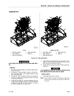
Removal
1. Disable machine operation.
2. Drain fuel from the fuel tank (1) and hydraulic tank
(2). Store fuel in appropriate receptacle.
3. Disconnect and cap the fuel and vent lines attached
to the fuel tank.
4. Remove the bolt and washer (3) securing fuel tank (1)
to hydraulic tray (4).
5. Remove the bolt and washers (3) securing hydraulic
tank (2) to hydraulic tray (4).
NOTE:
Fuel level switch needs disconnected
6. Remove the fuel tank (1) and hydraulic tank (2) from
the hydraulic compartment.
Installation
1. Follow Removal Steps in reverse.
NOTE:
If removed, before reinstalling into tank insert apply
pipe sealant (Medium Strength Threadlocking Com-
pound) to fuel and vent line fittings on the fuel tank
(1) and hydraulic tank (2). Torque all fittings to 10-14
ft. lbs. (13.6-20 Nm).
Torque hardware to 10 ft.lbs (13.6 Nm) to 14 ft. lbs.
(19 Nm).
Torque drain plug on fuel tank to 7 ft.lbs (9.5 Nm) to
9 ft.lbs (12.2 Nm)
2. Refill fuel tank with proper fuel.
ENSURE PROPER FUEL LINES ARE ATTACHED TO PROPER FITTING ON
FUEL TANK. FUEL TANK IS LABELED WITH RETURN LINE, SUPPLY LINE
AND VENT LINE.
3. Ensure there is no fuel leakage.
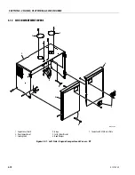
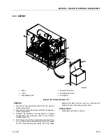
6.
Fuel Tank
7.
Hydraulic Tank
8.
Bolt and Washer
9.
Hydraulic Tray
10. Drain Plug
Figure 3-60. Tank Installation - RT
MAF42260D
1001248349-D
4
1
2
3
5
Summary of Contents for ERT2669
Page 2: ......
Page 4: ...INTRODUCTION A 2 31215923 REVISON LOG Original Issue A January 08 2021...
Page 12: ...viii 31215923 TABLE OF CONTENTS...
Page 40: ...SECTION 1 SPECIFICATIONS 1 22 31215923...
Page 58: ...SECTION 2 GENERAL 2 18 31215923...
Page 187: ...SECTION 4 BASIC HYDRAULIC INFORMATION SCHEMATICS 31215923 4 11...
Page 206: ...SECTION 4 BASIC HYDRAULIC INFORMATION SCHEMATICS 4 30 31215923...
Page 225: ...SECTION 4 BASIC HYDRAULIC INFORMATION SCHEMATICS 31215923 4 49...
Page 242: ...SECTION 4 BASIC HYDRAULIC INFORMATION SCHEMATICS 4 66 31215923...
Page 307: ...SECTION 5 JLG CONTROL SYSTEM 31215923 5 65...
Page 334: ...SECTION 6 LSS SETUP CALIBRATION SERVICE 6 12 31215923...
Page 362: ...SECTION 7 GENERAL ELECTRICAL INFORMATION SCHEMATICS 7 28 31215923...
Page 374: ...SECTION 7 GENERAL ELECTRICAL INFORMATION SCHEMATICS 7 40 31215923...
Page 375: ......


