SECTION 5 - JLG CONTROL SYSTEM
31215923
5-69
Rear Axle Tilt Sensor (Quiklevel Equipped Machines
Only)
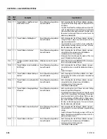
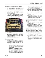
1. Place machine on flat level surface.
2. Start with machine in the stow position
3. Go to CALIBRATIONS > REAR AXLE TILT
4. Select Enter
5. Analyzer will state Level Vehicle?
6. Select Enter
7. Analyzer will state Unlock Axles?
8. Select Enter and a slight shutter will be felt as the
controller unlocks the rear axle.
9. The analyzer will remain on the Unlocking screen for
several seconds.
10. The analyzer will then display Calibrate Level?
11. Press Enter.
12. The calibrated Rear Axle Tilt will be shown for several
second and then calibration will automatically pro-
ceed to TILT LEFT TO MAX step.
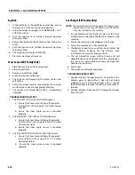
13. Use the Quiklevel Trim function by activating the
Steer Switches to Trim the machine all the way to the
left until the machine reaches end of stroke.
14. Press Enter
15. The analyzer will then display TILT RHT TO MAX step.
16. Use the Quiklevel Trim function by activating the
Steer Switches to Trim the machine all the way to the
right until the machine reaches end of stroke.
17. Press Enter
18. The analyzer will display Complete.
TROUBLESHOOTING STEPS
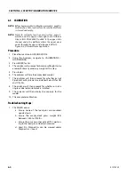
1. SENSOR FAILURE screen appears. Ensure there are no
DTC's active pertaining to the Front Axle Tilt Sensor
and that communication with the sensor is estab-
lished. Check for
a. Tilt sensor has moisture intrusion that has
shifted its output.
b. There is a wiring issue with the sensor.
c. Water and/or corrosion in the box has cor-
rupted electrical connections or caused a tilt
s e n s o r o r g ro u n d c o nt ro l b o a rd f a i l u re
(observe any cracks in the box).
2. CAL CHASSIS TILT failure occurs. Calibrate the chassis
tilt sensor first.
3. CAL FRONT AXLE TILT failure occurs. Calibrate the
front axle tilt sensor first.
4. NOT LEVEL screen appears: The rear axle tilt sensor
raw angles need to be within 1.0°, otherwise the
machine is not level and the software will prohibit
calibration. Should this occur, check for the follow-
ing:
a. Machine mounting and/or grade:
With a digital level, measure the front and rear
axles for levelness. The machine must be on
flat level ground.
b. Tilt sensor has developed an offset shift:
Remove the tilt sensor from the chassis, but
keep both the tilt sensor and Ground Control
box electrically connected. Level one axis of
the tilt sensor and observe the raw reading
(should be within ±2.0°). Do the same for the
other axis. If either axis is greater than ±2.0°,
replace the tilt sensor. Some possible reasons
that the tilt sensor will not calibrate are:
A. The surface the machine is sitting on is off level
by a few degrees (flat doesn't imply level; park-
ing lots are often not level).
B. The tilt sensor has failed one or both of the
channels (X axis and Y axis).
C. Tilt sensor has moisture intrusion that has
shifted its output.
D. Water and/or corrosion in the box has cor-
rupted electrical connections or caused a tilt
s e n s o r o r g ro u n d co n t ro l b o a rd f a i l u re
(observe any cracks in the box).
5. LF, RF, RL, RR NOT IN RANGE screens appear. This indi-
cates that the expected frame sway of the machine
for the corner that is being indicated as failed down
not fall within 4 to 6 degrees of frame sway as mea-
sured from chassis neutral to chassis tilted all the way
left or right. For example if RF NOT IN RANGE occurs
this indicates the calculated sway from chassis level
to full tilt right was either less than 4 degrees or
greater than 6 degrees. If this occurs:
a. Ensure the machine was completed tilted to
the left or right during the TILT LEFT TO MAX
and TILT RHT TO MAX steps.
b. Ensure there are no obstructions preventing
the machine from completely tiling left or
right.
c. Attempt to re-calibrate the chassis tilt sensor
and try again.
d. Attempt to re-calibrate the front axle tilt sen-
sor and try again.
Summary of Contents for ERT2669
Page 2: ......
Page 4: ...INTRODUCTION A 2 31215923 REVISON LOG Original Issue A January 08 2021...
Page 12: ...viii 31215923 TABLE OF CONTENTS...
Page 40: ...SECTION 1 SPECIFICATIONS 1 22 31215923...
Page 58: ...SECTION 2 GENERAL 2 18 31215923...
Page 187: ...SECTION 4 BASIC HYDRAULIC INFORMATION SCHEMATICS 31215923 4 11...
Page 206: ...SECTION 4 BASIC HYDRAULIC INFORMATION SCHEMATICS 4 30 31215923...
Page 225: ...SECTION 4 BASIC HYDRAULIC INFORMATION SCHEMATICS 31215923 4 49...
Page 242: ...SECTION 4 BASIC HYDRAULIC INFORMATION SCHEMATICS 4 66 31215923...
Page 307: ...SECTION 5 JLG CONTROL SYSTEM 31215923 5 65...
Page 334: ...SECTION 6 LSS SETUP CALIBRATION SERVICE 6 12 31215923...
Page 362: ...SECTION 7 GENERAL ELECTRICAL INFORMATION SCHEMATICS 7 28 31215923...
Page 374: ...SECTION 7 GENERAL ELECTRICAL INFORMATION SCHEMATICS 7 40 31215923...
Page 375: ......


