SECTION 5 - JLG CONTROL SYSTEM
31215923
5-67
Chassis Tilt Sensor - QuikLevel Equipped Machine
1. Drive the machine onto a measured level surface
(±0.5° for both x and y axis) and ensure the platform
is stowed.
2. Using the Analyzer, go to MENU: CALIBRATION; TILT
SENSOR. Press Enter. LEVEL VEHICLE will display.
Press Enter again to confirm that the vehicle is oper-
ating on flat level ground.
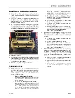
3. External Level On Machine will Display. At this step
ensure a digital level accurate to /- 0.25deg is
installed in the location shown below. This is the only
approved location for the digital level to be placed.
4. Press Enter Again.
5. At this step Trim to Level will be displayed. Activate
the Quiklevel Trim function using the steer switches
to trim the machine until the external level measured
to /- 0.1deg of level.
6. Press Enter again to complete calibration.
Troubleshooting Steps :
1. NOT LEVEL screen appears: Both front axle tilt sensor
and rear axle tilt sensor raw angles need to be within
2.0°, otherwise the machine is not level and the soft-
ware will prohibit calibration. Should this occur,
check for the following:
a.
Machine mounting and/or grade:
With a digital level, measure the front and rear
axles for levelness. The machine must be on
flat level ground.
b.
Tilt sensor has developed an offset shift:
Remove the tilt sensor from the chassis, but
keep both the tilt sensor and Ground Control
box electrically connected. Level one axis of
the tilt sensor and observe the raw reading
(should be within ±2.0°). Do the same for the
other axis. If either axis is greater than ±2.0°,
replace the tilt sensor. Some possible reasons
that the tilt sensor will not calibrate are:
A. The surface the machine is sitting on is off level
by a few degrees (flat doesn’t imply level; park-
ing lots are often not level).
B. The tilt sensor has failed one or both of the
channels (X axis and Y axis).
C. Tilt sensor has moisture intrusion that has
shifted its output.
D. Water and/or corrosion in the box has cor-
rupted electrical connections or caused a tilt
sensor or ground control board failure
(observe any cracks in the box).
2. SENSOR FAILURE screen appears. Ensure there are no
DTC's active pertaining to the Chassis Tilt Sensor and
that communication with the sensor is established.
Check for
a. Tilt sensor has moisture intrusion that has
shifted its output.
b. There is a wiring issue with the sensor.
c. Water and/or corrosion in the box has cor-
rupted electrical connections or caused a tilt
s e n s o r o r g ro u n d co n t ro l b o a rd f a i l u re
(observe any cracks in the box).
3. NOT IN TOLERANCE screen appears. Upon pressing
Enter at the Trim to Level step the raw chassis tilt sen-
sor output is not /- 1 degree. This can be
monitored by pressing the up/down or right/left
arrow keys at the YES:ENTER, NO:ESC screen. If this
occurs:
a. Ensure the chassis has been leveled properly
using the Quiklevel Trim function.
b. Ensure the chassis tilt sensor is mounted prop-
erly.
c. Ensure the external digital level is reading
accurate and has been placed in the proper
location.
Summary of Contents for ERT2669
Page 2: ......
Page 4: ...INTRODUCTION A 2 31215923 REVISON LOG Original Issue A January 08 2021...
Page 12: ...viii 31215923 TABLE OF CONTENTS...
Page 40: ...SECTION 1 SPECIFICATIONS 1 22 31215923...
Page 58: ...SECTION 2 GENERAL 2 18 31215923...
Page 187: ...SECTION 4 BASIC HYDRAULIC INFORMATION SCHEMATICS 31215923 4 11...
Page 206: ...SECTION 4 BASIC HYDRAULIC INFORMATION SCHEMATICS 4 30 31215923...
Page 225: ...SECTION 4 BASIC HYDRAULIC INFORMATION SCHEMATICS 31215923 4 49...
Page 242: ...SECTION 4 BASIC HYDRAULIC INFORMATION SCHEMATICS 4 66 31215923...
Page 307: ...SECTION 5 JLG CONTROL SYSTEM 31215923 5 65...
Page 334: ...SECTION 6 LSS SETUP CALIBRATION SERVICE 6 12 31215923...
Page 362: ...SECTION 7 GENERAL ELECTRICAL INFORMATION SCHEMATICS 7 28 31215923...
Page 374: ...SECTION 7 GENERAL ELECTRICAL INFORMATION SCHEMATICS 7 40 31215923...
Page 375: ......


