


SECTION 5 - JLG CONTROL SYSTEM
5-50
31215923
46199 4
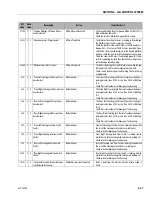
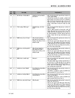
6 "Rear Right Module - Brake Coil Voltage
Feedback Incorrect"
Drive is Prevented.
• UGM is detecting that the Right Power Module is communi-
cating that there is a voltage issue with the Right Electric
Brake circuit.
• Check pins 7 and 8 of connector X424A for short to B-. Check
pins 2 and 4 of connector CO342-J1 for a short to B-. Check
pins 7 and 8 of the connector at the right rear drive motor for
a short to B-. If no issue is found with the wiring, then the
module may need replaced.
46200 4
6 "Rear Left Module - Brake Coil Voltage
Feedback Incorrect"
Drive is Prevented.
• UGM is detecting that the Left Power Module is communi-
cating that there is a voltage issue with the Left Electric
Brake circuit.
• Check pins 7 and 8 of connector X425A for short to B-. Check
pins 2 and 4 of connector CO371-J1 for a short to B-. Check
pins 7 and 8 of the connector at the left rear drive motor for a
short to B-.
• If no issue is found with the wiring, then the module may
need replaced.
46201 4
6 "Rear Right Module - Brake Coil Supply
Open Circuit"
Drive is Prevented.
• UGM is detecting that the Right Power Module is communi-
cating that the Right Electric Brake Supply Voltage is reading
as an open voltage.
• Check connector CO342-J1 Pin 3 for 48V. The pin should have
continuity to the B+ terminal on the module. Check fuse F8
in the fuse box. Check all wiring between B+ terminal and
CO342-J1 connector for damage.
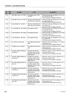
46202 4
6 "Rear Left Module - Brake Coil Supply
Open Circuit"
Drive is Prevented.
• UGM is detecting that the Left Power Module is communi-
cating that the Left Electric Brake Supply Voltage is reading
as an open voltage.
• Check connector CO371-J1 Pin 3 for 48V. The pin should have
continuity to the B+ terminal on the module. Check fuse F9
in the fuse box. Check all wiring between B+ terminal and
CO371-J1 connector for damage.
46203 4
6 "Rear Right Module - Drive Direction Com-
mand Error"
Drive is Prevented.
• UGM is detecting that the Right Power Module is seeing
both a Forward and Reverse Drive command from the UGM.
• Contact JLG Support.
46204 4
6 "Rear Left Module - Drive Direction Com-
mand Error"
Drive is Prevented.
• UGM is detecting that the Left Power Module is seeing both
a Forward and Reverse Drive command from the UGM.
• Contact JLG Support.
46205 4
6 "Rear Right Module - Steer Sensor Voltage
Out Of Range"
Drive Speed is Restricted to Elevated
Speed.
• UGM is detecting that the Right Power Module is communi-
cating that the Steer Sensor Output Voltage is outside the
acceptable value range.
• Ensure the Steer Sensor is calibrated. Check that the steer
sensor is properly mounted on the axle. Check the wiring
and connections between the steer sensor and module con-
nector CO342-J1 for damage. Check continuity between
steer cable (SN353 - X423B) and traction harness (X423A -
CO342-J1). If no issue with the wiring, then the steer sensor
may need replaced.
DTC
Code
Flash
Code
Description
Action
Item Check List
Summary of Contents for ERT2669
Page 2: ......
Page 4: ...INTRODUCTION A 2 31215923 REVISON LOG Original Issue A January 08 2021...
Page 12: ...viii 31215923 TABLE OF CONTENTS...
Page 40: ...SECTION 1 SPECIFICATIONS 1 22 31215923...
Page 58: ...SECTION 2 GENERAL 2 18 31215923...
Page 187: ...SECTION 4 BASIC HYDRAULIC INFORMATION SCHEMATICS 31215923 4 11...
Page 206: ...SECTION 4 BASIC HYDRAULIC INFORMATION SCHEMATICS 4 30 31215923...
Page 225: ...SECTION 4 BASIC HYDRAULIC INFORMATION SCHEMATICS 31215923 4 49...
Page 242: ...SECTION 4 BASIC HYDRAULIC INFORMATION SCHEMATICS 4 66 31215923...
Page 307: ...SECTION 5 JLG CONTROL SYSTEM 31215923 5 65...
Page 334: ...SECTION 6 LSS SETUP CALIBRATION SERVICE 6 12 31215923...
Page 362: ...SECTION 7 GENERAL ELECTRICAL INFORMATION SCHEMATICS 7 28 31215923...
Page 374: ...SECTION 7 GENERAL ELECTRICAL INFORMATION SCHEMATICS 7 40 31215923...
Page 375: ......


