


SECTION 3 - CHASSIS, PLATFORM, & SCISSOR ARMS
3-22
31215923
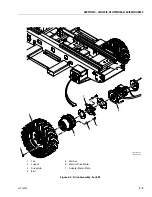
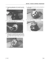
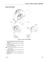
4. Place thrust washer (11) around spindle (1A) so it
rests on the bottom of the internal gear (2).
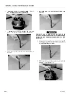
5. Stand input shaft (7A) on its splined end. Place one
spacer (7D) onto the smooth end of input shaft (7A).
6. Place one spring (7C) onto the smooth end of input
shaft (7A).
7. Place other spacer (7D) onto the smooth end of input
shaft (7A).
WEAR SAFETY GLASSES DURING THIS STEP, AND BE AWARE THAT
SPRING AND SPACERS, COMPRESSED BY RETAINING RING, MAY POP
SUDDENLY OFF SHAFT IF THE RING IS RELEASED BEFORE IT IS PROP-
ERLY IN PLACE.
8. Using retaining ring pliers, insert retaining ring (7B)
into the groove on input shaft (7A) by compressing
the spring and spacers together.
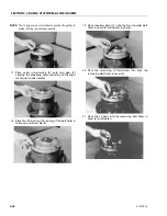
9. With large splined end down, place input shaft sub-
assembly (7) into spindle (1A).
Summary of Contents for ERT2669
Page 2: ......
Page 4: ...INTRODUCTION A 2 31215923 REVISON LOG Original Issue A January 08 2021...
Page 12: ...viii 31215923 TABLE OF CONTENTS...
Page 40: ...SECTION 1 SPECIFICATIONS 1 22 31215923...
Page 58: ...SECTION 2 GENERAL 2 18 31215923...
Page 187: ...SECTION 4 BASIC HYDRAULIC INFORMATION SCHEMATICS 31215923 4 11...
Page 206: ...SECTION 4 BASIC HYDRAULIC INFORMATION SCHEMATICS 4 30 31215923...
Page 225: ...SECTION 4 BASIC HYDRAULIC INFORMATION SCHEMATICS 31215923 4 49...
Page 242: ...SECTION 4 BASIC HYDRAULIC INFORMATION SCHEMATICS 4 66 31215923...
Page 307: ...SECTION 5 JLG CONTROL SYSTEM 31215923 5 65...
Page 334: ...SECTION 6 LSS SETUP CALIBRATION SERVICE 6 12 31215923...
Page 362: ...SECTION 7 GENERAL ELECTRICAL INFORMATION SCHEMATICS 7 28 31215923...
Page 374: ...SECTION 7 GENERAL ELECTRICAL INFORMATION SCHEMATICS 7 40 31215923...
Page 375: ......


