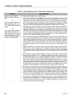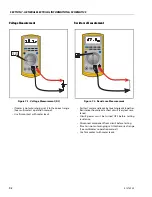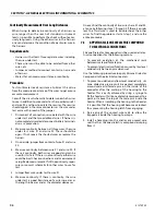
SECTION 7 - GENERAL ELECTRICAL INFORMATION & SCHEMATICS
31215923
7-9
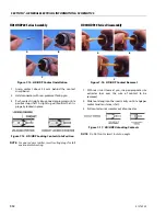
Disassembly
1. Insert a 4.8 mm (3/16 in.) wide screwdriver blade
between the mating seal and one of the red wedge
lock tabs.
2. Pry open the wedge lock to the open position.
3. While rotating the wire back and forth over a half
turn (1/4 turn in each direction), gently pull the wire
until the contact is removed.
NOTE:
The wedge lock should never be removed from the
housing for insertion or removal of the contacts.
Wedge Lock
The wedge lock has slotted openings in the forward, or
mating end. These slots accommodate circuit testing in
the field, by using a flat probe such as a pocket knife. DO
NOT use a sharp point such as an ice pick.
Figure 7-10. Connector Disassembly
Summary of Contents for ERT2669
Page 2: ......
Page 4: ...INTRODUCTION A 2 31215923 REVISON LOG Original Issue A January 08 2021...
Page 12: ...viii 31215923 TABLE OF CONTENTS...
Page 40: ...SECTION 1 SPECIFICATIONS 1 22 31215923...
Page 58: ...SECTION 2 GENERAL 2 18 31215923...
Page 187: ...SECTION 4 BASIC HYDRAULIC INFORMATION SCHEMATICS 31215923 4 11...
Page 206: ...SECTION 4 BASIC HYDRAULIC INFORMATION SCHEMATICS 4 30 31215923...
Page 225: ...SECTION 4 BASIC HYDRAULIC INFORMATION SCHEMATICS 31215923 4 49...
Page 242: ...SECTION 4 BASIC HYDRAULIC INFORMATION SCHEMATICS 4 66 31215923...
Page 307: ...SECTION 5 JLG CONTROL SYSTEM 31215923 5 65...
Page 334: ...SECTION 6 LSS SETUP CALIBRATION SERVICE 6 12 31215923...
Page 362: ...SECTION 7 GENERAL ELECTRICAL INFORMATION SCHEMATICS 7 28 31215923...
Page 374: ...SECTION 7 GENERAL ELECTRICAL INFORMATION SCHEMATICS 7 40 31215923...
Page 375: ......


