


SECTION 5 - JLG CONTROL SYSTEM
31215923
5-33
6651
6
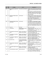
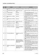
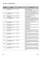
6 “CANBUS Failure - Ground Display”
No response.
• UGM is detecting that CAN Communication has been lost
with the Ground Display.
• Check ground display connector for damage and faulty wir-
ing. Check for 12V on PWR and GND wires with machine
powered on. Measure between the CAN wires for 60 ohms, if
not then CAN wires/circuit have damage. If above checks out
okay, then Display may need replaced.
666
6
6 “CANBUS Failure - Engine Controller”
Lift Up, Quik Level, Generator and
Level Jack Extend Functions Pre-
vented. Drive allowed in Elevated
Speed.
• UGM is detecting that CAN Communication has been lost
with the ECU Module.
• Check ECU for damage and faulty wiring. Check for 12V on
PWR and GND wires with machine powered on. Measure
between the CAN wires for 60 ohms, if not then CAN wires/
circuit have damage. If above checks out okay, then ECU may
need replaced.
6661
6
6 “CANBUS Failure - Arm Stack Tilt Sensor”
Lift Up Prevented.
• UGM is detecting that CAN Communication has been lost
with the Arm Stack Tilt Sensor.
• Check Tilt sensor connector for damage and faulty wiring.
Check for 12V on PWR and GND wires with machine powered
on. Measure between the CAN wires for 60 ohms, if not then
CAN wires/circuit have damage. If above checks out okay,
then Tilt Sensor may need replaced.
6698
6
6 “CANBUS Failure - Rear Oscillating Axle Tilt
Sensor"
Lift Up and Quik Level Functions Pre-
vented. Drive is prevented if the
Machine is Not Stowed.
• UGM is detecting that CAN Communication has been lost
with the Rear Axle Tilt Sensor.
• Check Tilt sensor connector for damage and faulty wiring.
Check for 12V on PWR and GND wires with machine powered
on. Measure between the CAN wires for 60 ohms, if not then
CAN wires/circuit have damage. If above checks out okay,
then Tilt Sensor may need replaced.
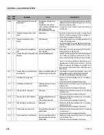
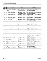
8113
8
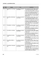
1 “Front Axle Tilt Sensor Has Not Calibrated” Lift Up is Prevented. Drive is pre-
vented if the Machine is Not Stowed.
• The UGM is detecting that the Front Axle Tilt Sensor does not
have a Calibrated Value in Memory.
8114
8
1 “Arm Stack Tilt Sensor Out Of Range”
Lift Up is Prevented.
• The UGM is detecting that the Arm Stack Tilt Sensor Value is
reading greater than 80° or less than -15°.
• Check sensor for damage or faulty wiring.
8115
8
1 “Front Axle Tilt Sensor Out Of Range”
Lift Up is Prevented. Drive is pre-
vented if the Machine is Not Stowed.
Axle Tilt Calibration Prevented.
• The UGM is detecting that the Front Axle Tilt Sensor Value is
reading greater than +/- 30°
• Check sensor for damage or faulty wiring.
8118
8
1 “Front Axle Tilt Sensor Stagnant”
Lift Up is Prevented. Drive is pre-
vented if the Machine is Not Stowed.
Axle Tilt Calibration Prevented.
• The UGM is detecting that the Front Axle Tilt Sensor Value is
not changing during Drive.
• Check sensor for damage or faulty wiring.
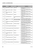
8120
8
1 “Arm Stack Tilt Sensor - Disagreement"
Lift Up is Prevented.
• The Arm Stack Tilt Sensor has an internal accelerometer dis-
agreement. Tilt Sensor will need replaced.
8121
8
1 “Front Axle Tilt Sensor - Disagreement”
Lift Up is Prevented. Drive is pre-
vented if the Machine is Not Stowed.
• The Front Axle Tilt Sensor has an internal accelerometer dis-
agreement. Tilt Sensor will need replaced.
8122
8
1 “Rear Axle Tilt Sensor Out Of Range”
Lift Up and Quik Level Functions Pre-
vented. Drive is prevented if the
Machine is Not Stowed.
• The UGM is detecting that the Rear Axle Tilt Sensor Value is
reading greater than +/- 30°.
• Check sensor for damage or faulty wiring.
8123
8
1 “Rear Axle Tilt Sensor - Disagreement”
Lift Up and Quik Level Functions Pre-
vented. Drive is prevented if the
Machine is Not Stowed.
• The Rear Axle Tilt Sensor has an internal accelerometer dis-
agreement. Tilt Sensor will need replaced.
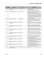
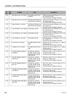
DTC
Code
Flash
Code
Description
Action
Item Check List
Summary of Contents for ERT2669
Page 2: ......
Page 4: ...INTRODUCTION A 2 31215923 REVISON LOG Original Issue A January 08 2021...
Page 12: ...viii 31215923 TABLE OF CONTENTS...
Page 40: ...SECTION 1 SPECIFICATIONS 1 22 31215923...
Page 58: ...SECTION 2 GENERAL 2 18 31215923...
Page 187: ...SECTION 4 BASIC HYDRAULIC INFORMATION SCHEMATICS 31215923 4 11...
Page 206: ...SECTION 4 BASIC HYDRAULIC INFORMATION SCHEMATICS 4 30 31215923...
Page 225: ...SECTION 4 BASIC HYDRAULIC INFORMATION SCHEMATICS 31215923 4 49...
Page 242: ...SECTION 4 BASIC HYDRAULIC INFORMATION SCHEMATICS 4 66 31215923...
Page 307: ...SECTION 5 JLG CONTROL SYSTEM 31215923 5 65...
Page 334: ...SECTION 6 LSS SETUP CALIBRATION SERVICE 6 12 31215923...
Page 362: ...SECTION 7 GENERAL ELECTRICAL INFORMATION SCHEMATICS 7 28 31215923...
Page 374: ...SECTION 7 GENERAL ELECTRICAL INFORMATION SCHEMATICS 7 40 31215923...
Page 375: ......


