


SECTION 7 - GENERAL ELECTRICAL INFORMATION & SCHEMATICS
31215923
7-3
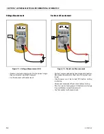
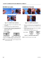
Continuity Measurement
• Some meters require a separate button press to
enable audible continuity testing.
• Circuit power must be turned OFF before testing
continuity.
• Disconnect component from circuit before testing.
• Use firm contact with meter leads.
• First test meter and leads by touching leads together.
Meter should produce an audible alarm, indicating
continuity.
Current Measurement
• Set up the meter for the expected current range.
• Be sure to connect the meter leads to the correct
jacks for the current range you have selected.
• If meter is not auto ranging, set it to the correct range
(See multi meter’s operation manual).
• Use firm contact with meter leads.
Figure 7-3. Continuity Measurement
Figure 7-4. Current Measurement (DC)
Summary of Contents for ERT2669
Page 2: ......
Page 4: ...INTRODUCTION A 2 31215923 REVISON LOG Original Issue A January 08 2021...
Page 12: ...viii 31215923 TABLE OF CONTENTS...
Page 40: ...SECTION 1 SPECIFICATIONS 1 22 31215923...
Page 58: ...SECTION 2 GENERAL 2 18 31215923...
Page 187: ...SECTION 4 BASIC HYDRAULIC INFORMATION SCHEMATICS 31215923 4 11...
Page 206: ...SECTION 4 BASIC HYDRAULIC INFORMATION SCHEMATICS 4 30 31215923...
Page 225: ...SECTION 4 BASIC HYDRAULIC INFORMATION SCHEMATICS 31215923 4 49...
Page 242: ...SECTION 4 BASIC HYDRAULIC INFORMATION SCHEMATICS 4 66 31215923...
Page 307: ...SECTION 5 JLG CONTROL SYSTEM 31215923 5 65...
Page 334: ...SECTION 6 LSS SETUP CALIBRATION SERVICE 6 12 31215923...
Page 362: ...SECTION 7 GENERAL ELECTRICAL INFORMATION SCHEMATICS 7 28 31215923...
Page 374: ...SECTION 7 GENERAL ELECTRICAL INFORMATION SCHEMATICS 7 40 31215923...
Page 375: ......


