SECTION 3 - CHASSIS, PLATFORM, & SCISSOR ARMS
3-98
31215923
ALLOW ENGINE AND COMPONENTS TO COOL DOWN BEFORE SERVIC-
ING.
REMOVAL
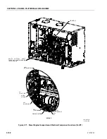
1. Disable machine operation. Open engine cabinet
doors to get access to generator.
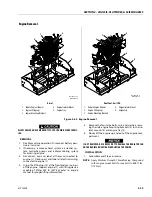
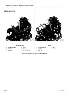
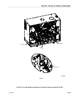
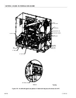
2. Disconnect and label electrical wires attached to
generator (1).
3. Remove the hardware securing generator belt cover
to generator mount to get access to generator pul-
ley.
4. Remove the hardware securing generator adjust
bracket (3) to generator mount (5).
5. Loosen the eye bolt rod to remove the belt tension.
6. Then remove hardware securing generator adjust
bracket (3) to generator (1)
7. Remove 2 bolts securing hydraulic pump to coupler
housing and slide hydraulic pump from splined con-
nection.
8. Remove the hardware securing generator (1) to gen-
erator mount (5). remove generator (1).
9. If necessary, remove generator mount (5) from the
machine by removing all hardware.
INSTALLATION
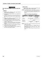
1. Follow Removal Steps in reverse. Ensure belt is tight
before securing generator with the bolts.
NOTE:
Apply Medium Strength Threadlocking Compound
to the threads of the generator mounting bolts. Use
threaded eyebolt to adjust the belt tension to 167 lbs
(743 N)
NOTE:
The generator control box is located on the side wall
of the engine cabinet.
The platform junction box is mounted under the
platform deck on the Hydraulic/Fuel Tank cabinet
side of the machine.
See Section 7, General Electrical Information & Sche-
matics.
Table 3-16. AC Generator Specifications
DESCRIPTION
2300 kw 60 Hz
2300 kw 50 Hz
Voltage
99-121 VAC
220 VAC (Unloaded)
238 VAC (Loaded)
Continuous
2185-2415 kw @ 60 Hz,
26.7 °C
2190 kw @ 50 Hz, 26.7 °C
Peak Speed
10,000 rpm
Rated Current
21.85-24.15 Amps @
110 VAC
9.15-9.25 Amps @ 238
VAC
Summary of Contents for ERT2669
Page 2: ......
Page 4: ...INTRODUCTION A 2 31215923 REVISON LOG Original Issue A January 08 2021...
Page 12: ...viii 31215923 TABLE OF CONTENTS...
Page 40: ...SECTION 1 SPECIFICATIONS 1 22 31215923...
Page 58: ...SECTION 2 GENERAL 2 18 31215923...
Page 187: ...SECTION 4 BASIC HYDRAULIC INFORMATION SCHEMATICS 31215923 4 11...
Page 206: ...SECTION 4 BASIC HYDRAULIC INFORMATION SCHEMATICS 4 30 31215923...
Page 225: ...SECTION 4 BASIC HYDRAULIC INFORMATION SCHEMATICS 31215923 4 49...
Page 242: ...SECTION 4 BASIC HYDRAULIC INFORMATION SCHEMATICS 4 66 31215923...
Page 307: ...SECTION 5 JLG CONTROL SYSTEM 31215923 5 65...
Page 334: ...SECTION 6 LSS SETUP CALIBRATION SERVICE 6 12 31215923...
Page 362: ...SECTION 7 GENERAL ELECTRICAL INFORMATION SCHEMATICS 7 28 31215923...
Page 374: ...SECTION 7 GENERAL ELECTRICAL INFORMATION SCHEMATICS 7 40 31215923...
Page 375: ......

