6 - 5
Replacement
(continued)
5
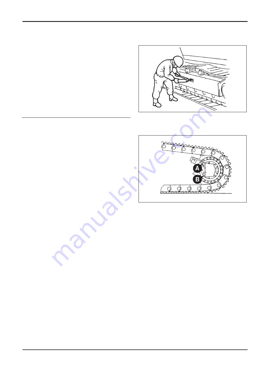
Apply grease through the check valve to adjust the
track tension
(see
Tracks and Running Gear,
Checking/Adjusting the Track Tension
, Section 3).
Motor Bleeding
Bleeding must be done whenever a track motor is being
fitted.
Note:
If a track gearbox assembly is being fitted to the
machine with the motor attached, follow the procedure given
under
Track Gearbox Removal and Replacement
.
When the motor is being fitted to a gearbox already fitted to
the machine, bleed the air from the motor by one of the three
methods detailed below.
Note:
Method
1
will take considerable time as air in the
motor is very difficult to purge. Methods
2
or
3
may be
quicker.
Method 1
After fitting the motor but before connecting the pipework,
remove plug from upper drain port
A
but make sure that a
plug is fitted to lower drain port
B
.
Fill the motor with specified hydraulic oil through port
A
.
Connect the pipes.
Method 2
Fit the motor and connect all pipes except the two drains.
Remove plug from port
A
. Make sure that a steel plug is
fitted to bottom drain port
B
.
Run the engine and operate the track control lever slightly so
that the sprocket does not turn. If necessary, prevent the
sprocket from turning by means of a steel bar or tube
jammed in the track. Return the lever to neutral when air-
free oil flows from port
A
. Connect the drain pipes.
Method 3
Fit the motor and connect all pipes. Prevent the sprocket
from turning by means of a steel bar or tube jammed in the
track. Run the engine and fully select the track control lever
for about 1 minute. This will fill the motor case with oil.
Section F
Transmission
9803/6400
Section F
6 - 5
Issue 2*
Motor/Gearbox
*
Summary of Contents for JS 200 Series
Page 57: ...9 1 Section 3 Routine Maintenance 9803 6400 Section 3 9 1 Issue 2 Component Location Diagram...
Page 113: ......
Page 137: ...5 3 Section C Electrics 9803 6400 Section C 5 3 Issue 2 Pump Control FLOW CHART...
Page 201: ...10 7 Section C Electrics 9803 6400 Section C 10 7 Issue 1 CAPs II Diagnostic system K C...
Page 215: ...Section E Section E Hydraulics 9803 6400 Issue 2 3 2 3 2 Schematics...
Page 217: ...Section E Section E 9803 6400 Issue 2 3 3 3 3 Hydraulics Schematics...
Page 218: ...3 5 Section E Hydraulics 9803 6400 Section E 3 5 Issue 1 Schematics Shuttle Block JS200 JS240...
Page 232: ...10 1 Section E Hydraulics 9803 6400 Section E 10 1 Issue 1 Hydraulic Pump JS200 JS240...
Page 233: ...10 2 Section E Hydraulics 9803 6400 Section E 10 2 Issue 1 Hydraulic Pump JS200 JS240...
Page 234: ...10 3 Section E Hydraulics 9803 6400 Section E 10 3 Issue 1 Hydraulic Pump JS200 JS240...
Page 263: ...30 2 Section E Hydraulics 9803 6400 Section E 30 2 Issue 1 Control Valve JS200 JS240...
Page 264: ...30 3 Section E Hydraulics 9803 6400 Section E 30 3 Issue 1 Control Valve JS200 JS240...
Page 265: ...30 4 Section E Hydraulics 9803 6400 Section E 30 4 Issue 1 Control Valve JS200 JS240...
Page 266: ...30 5 Section E Hydraulics 9803 6400 Section E 30 5 Issue 1 Control Valve JS200 JS240...
Page 267: ...30 6 Section E Hydraulics 9803 6400 Section E 30 6 Issue 1 Control Valve JS200 JS240...
Page 268: ...30 7 Section E Hydraulics 9803 6400 Section E 30 7 Issue 1 Control Valve JS200 JS240...
Page 327: ...51 12 Section E Hydraulics 9803 6400 Section E 51 12 Issue 1 Solenoid Valve 8 spool...
Page 328: ...55 1 Schematic Section E Hydraulics 9803 6400 Section E 55 1 Issue 1 Shuttle Valve...
Page 330: ...55 3 Schematic Section E Hydraulics 9803 6400 Section E 55 3 Issue 1 Cushion Valves...
Page 481: ...7 15 Section F Transmission 9803 6400 Section F 7 15 Issue 2 Motor...
Page 482: ...7 16 Section F Transmission 9803 6400 Section F 7 16 Issue 1 Motor...


