3 - 9
Section F
Transmission
9803/6400
Section F
3 - 9
Issue 1
Motor/Gearbox
Operation
(continued)
Automatic 2-speed
Refer to Fig. 8-1
With pilot pressure
Ps = 0
, the 2-speed valve is maintained in the position as illustrated and the motor speed is first, or low.
Refer to Fig. 8-2
During travel on level ground when the motor load pressure is below the set pressure
P
, if pilot pressure
Ps
is operated, the
pressure inside cavity
B
of the 2-speed valve is low, (
F2<F1
) and the 2-speed valve is held in the illustrated state and the motor
speed changes to second or high.
Refer to Fig. 8-3
When the motor load pressure rises and reaches the set pressure
P
after going uphill or steering operations are done with the
pilot pressure
Ps
operated, the pressure inside cavity
B
of the 2-speed valve also rises, (
F2>F1
) and the 2-speed valve moves
to the state shown and the motor speed changes to first or low.
When the motor drive pressure drops lower than the set pressure
P
, the pressure inside cavity
B
of the 2-speed valve also
drops (
F2<F1
), the 2-speed valve moves as shown in Fig. 8-2 and the motor speed changes to second, or high.
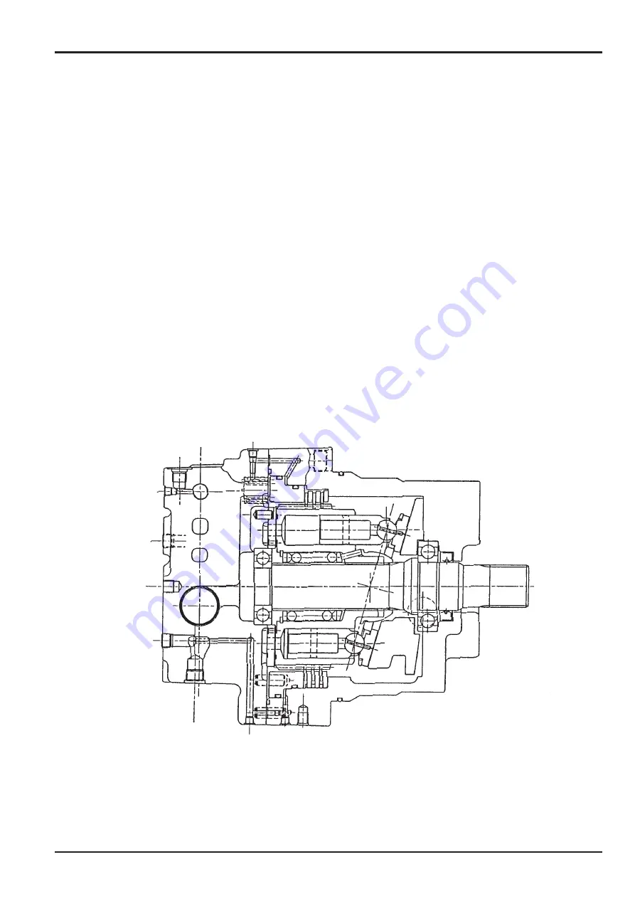
Parking Brake
The parking brake is a pressurised off type comprising a disk (wear-resistant material) as the rotary section, brake piston and
spring.
Refer to Fig. 9
As explained on page F/3-6 at the shuttle function of the counterbalance valve, pressurised oil is guided to the cylinder cavity
for parking brake release through port
P3
. The force corresponding to the pressure receiving area is fed to the brake piston.
This force overcomes the spring force to press the brake piston upward, and this releases the parking brake. When parking or
stopping the machine, the pressurised oil in the parking brake cylinder is released to the motor case drain, and the brake piston
is pushed by the spring force, applying the parking brake.
Fig. 9 Parking Brake
Summary of Contents for JS 200 Series
Page 57: ...9 1 Section 3 Routine Maintenance 9803 6400 Section 3 9 1 Issue 2 Component Location Diagram...
Page 113: ......
Page 137: ...5 3 Section C Electrics 9803 6400 Section C 5 3 Issue 2 Pump Control FLOW CHART...
Page 201: ...10 7 Section C Electrics 9803 6400 Section C 10 7 Issue 1 CAPs II Diagnostic system K C...
Page 215: ...Section E Section E Hydraulics 9803 6400 Issue 2 3 2 3 2 Schematics...
Page 217: ...Section E Section E 9803 6400 Issue 2 3 3 3 3 Hydraulics Schematics...
Page 218: ...3 5 Section E Hydraulics 9803 6400 Section E 3 5 Issue 1 Schematics Shuttle Block JS200 JS240...
Page 232: ...10 1 Section E Hydraulics 9803 6400 Section E 10 1 Issue 1 Hydraulic Pump JS200 JS240...
Page 233: ...10 2 Section E Hydraulics 9803 6400 Section E 10 2 Issue 1 Hydraulic Pump JS200 JS240...
Page 234: ...10 3 Section E Hydraulics 9803 6400 Section E 10 3 Issue 1 Hydraulic Pump JS200 JS240...
Page 263: ...30 2 Section E Hydraulics 9803 6400 Section E 30 2 Issue 1 Control Valve JS200 JS240...
Page 264: ...30 3 Section E Hydraulics 9803 6400 Section E 30 3 Issue 1 Control Valve JS200 JS240...
Page 265: ...30 4 Section E Hydraulics 9803 6400 Section E 30 4 Issue 1 Control Valve JS200 JS240...
Page 266: ...30 5 Section E Hydraulics 9803 6400 Section E 30 5 Issue 1 Control Valve JS200 JS240...
Page 267: ...30 6 Section E Hydraulics 9803 6400 Section E 30 6 Issue 1 Control Valve JS200 JS240...
Page 268: ...30 7 Section E Hydraulics 9803 6400 Section E 30 7 Issue 1 Control Valve JS200 JS240...
Page 327: ...51 12 Section E Hydraulics 9803 6400 Section E 51 12 Issue 1 Solenoid Valve 8 spool...
Page 328: ...55 1 Schematic Section E Hydraulics 9803 6400 Section E 55 1 Issue 1 Shuttle Valve...
Page 330: ...55 3 Schematic Section E Hydraulics 9803 6400 Section E 55 3 Issue 1 Cushion Valves...
Page 481: ...7 15 Section F Transmission 9803 6400 Section F 7 15 Issue 2 Motor...
Page 482: ...7 16 Section F Transmission 9803 6400 Section F 7 16 Issue 1 Motor...


