33 - 1
Section E
Hydraulics
9803/6400
Section E
33 - 1
Issue 2*
Control Valve JS200/JS240
These procedures refer to the sectional drawings at the beginning of this section.
Dismantling
Notes:
1.
All parts are manufactured with a high degree of precision and require the utmost care when handling. Do not let parts
knock against each other and take extra precautions when handling parts to prevent them being dropped.
2.
During dismantling, do not hit parts with excessive force if they are stuck and do not damage parts by twisting them or
making burrs on bearing surfaces. Failure to follow these instructions will cause oil leaks leading to poor performance.
3.
Label all parts during dismantling to ensure correct assembly.
4.
Storing of the control valve in a dismantled or partly dismantled state could cause rusting of parts due to moisture or dirt. If
the dismantling procedure must be interrupted, be sure to provide anti-rust treatment and keep the parts free from dirt and
corrosion.
5.
During assembly ensure that all parts are free from dirt and foreign matter and
make sure that all parts are free from burrs and scratches. Remove minor
burrs and scratches using and oil stone.
6.
Use new 'O' rings and back-up rings.
7.
During assembly, apply grease to 'O' rings.
8.
Tighten all bolts to the quoted tightening torque.
9.
Refer to the Control Valve Schematics when dismantling and assembly.
Dismantling, 5-spool control valve section
1.
Loosen and remove the socket head bolts 58, 59 of the caps 11, 14.
Be careful that the 'O'-ring 7 15 does not fall off, and remove the
bolts from the cap.
2.
Pull out spools 2, 3, 4, 5, 6 from the valve housing 1 in the sub-assembly state.
3.
Because each spool end has adhesive coating on the thread portion, heat the spool outer periphery at the threaded section
to about 200~250 °C and loosen the spool end, plugs, etc. immediately after heating.
4.
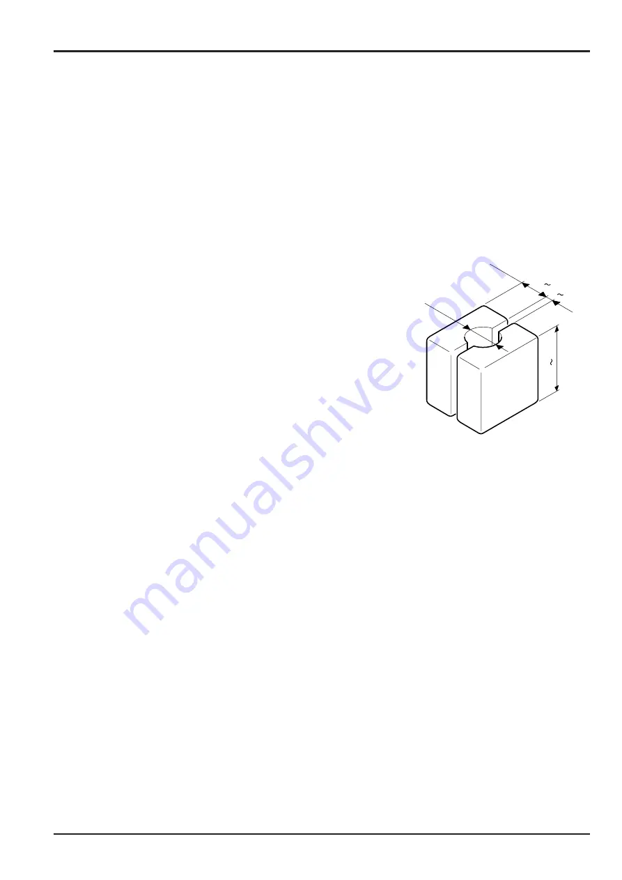
In order not to damage the spool periphery, insert the spool between hard wooden blocks shown above and fix in a vice
during work.
5.
Heat the spool 2 and remove the plug 16 (hexagonal A/F 24) and take out the spring 19 and poppet 20 from inside the
spool.
6.
Do not reuse the 'O'-ring 17 because heating was used during disassembly.
7.
Heat spools 3, 4, 5, 6 and loosen the spool end 10 (Hexagonal A/F 22). Disassemble the spring seat 8 and springs 9, 68.
8.
Attach tags to the springs 9, 68 and each spool to ensure correct assembly position and direction during reassembly.
9.
Heat the spool 3 and remove the plug 19 (Hexagonal 24 A/F). Take out the spring 22 and poppet 23 from inside the
spool and remove the 'O'-ring 21 and backup ring 20.
10.
Do not reuse the 'O'-ring 21 and backup ring 20 because heating was used during disassembly.
11.
Take out the spool 7 and spring seat 9 from the valve housing 1.
12.
Take out the plug 35 (M10) from the valve housing and remove the 'O'-ring 37 and backup ring 36. Be careful not to lose
the poppet 58.
13.
Take out the spacer assembly 55, spring 38, poppet 39 and sleeve 40 from the valve housing and remove the 'O'-ring 41
and backup ring 42.
14.
Remove the check valve assembly 32 (Hexagonal 36 A/F).
15.
Take out the sleeve 33, spring 26 and poppet 25 from the valve housing 1.
16.
Loosen the plug 43 (Hexagonal 27 A/F) and remove the 'O'-ring 44, spring 45 and poppet 46.
17.
Loosen the plug 30 (Hexagonal 27 A/F) and remove the 'O'-ring 29, spring 22 and poppet 27.
JS03730
¿28
30 40
3 6
70 100
*
Summary of Contents for JS 200 Series
Page 57: ...9 1 Section 3 Routine Maintenance 9803 6400 Section 3 9 1 Issue 2 Component Location Diagram...
Page 113: ......
Page 137: ...5 3 Section C Electrics 9803 6400 Section C 5 3 Issue 2 Pump Control FLOW CHART...
Page 201: ...10 7 Section C Electrics 9803 6400 Section C 10 7 Issue 1 CAPs II Diagnostic system K C...
Page 215: ...Section E Section E Hydraulics 9803 6400 Issue 2 3 2 3 2 Schematics...
Page 217: ...Section E Section E 9803 6400 Issue 2 3 3 3 3 Hydraulics Schematics...
Page 218: ...3 5 Section E Hydraulics 9803 6400 Section E 3 5 Issue 1 Schematics Shuttle Block JS200 JS240...
Page 232: ...10 1 Section E Hydraulics 9803 6400 Section E 10 1 Issue 1 Hydraulic Pump JS200 JS240...
Page 233: ...10 2 Section E Hydraulics 9803 6400 Section E 10 2 Issue 1 Hydraulic Pump JS200 JS240...
Page 234: ...10 3 Section E Hydraulics 9803 6400 Section E 10 3 Issue 1 Hydraulic Pump JS200 JS240...
Page 263: ...30 2 Section E Hydraulics 9803 6400 Section E 30 2 Issue 1 Control Valve JS200 JS240...
Page 264: ...30 3 Section E Hydraulics 9803 6400 Section E 30 3 Issue 1 Control Valve JS200 JS240...
Page 265: ...30 4 Section E Hydraulics 9803 6400 Section E 30 4 Issue 1 Control Valve JS200 JS240...
Page 266: ...30 5 Section E Hydraulics 9803 6400 Section E 30 5 Issue 1 Control Valve JS200 JS240...
Page 267: ...30 6 Section E Hydraulics 9803 6400 Section E 30 6 Issue 1 Control Valve JS200 JS240...
Page 268: ...30 7 Section E Hydraulics 9803 6400 Section E 30 7 Issue 1 Control Valve JS200 JS240...
Page 327: ...51 12 Section E Hydraulics 9803 6400 Section E 51 12 Issue 1 Solenoid Valve 8 spool...
Page 328: ...55 1 Schematic Section E Hydraulics 9803 6400 Section E 55 1 Issue 1 Shuttle Valve...
Page 330: ...55 3 Schematic Section E Hydraulics 9803 6400 Section E 55 3 Issue 1 Cushion Valves...
Page 481: ...7 15 Section F Transmission 9803 6400 Section F 7 15 Issue 2 Motor...
Page 482: ...7 16 Section F Transmission 9803 6400 Section F 7 16 Issue 1 Motor...


