3. Processor Bus Interface
84
PowerSpan II User Manual
80A1010_MA001_09
Integrated Device Technology
www.idt.com
3.2.2
PB Bus Interface Descriptions
The PB Bus Interface is described in terms of its master and slave functions. The PCI interfaces on
PowerSpan II are described in terms of its PCI master and PCI target functions. This description is
largely independent of PCI-1 versus PCI-2, or the assignment of the Primary PCI Interface functions.
Exceptions to these rules are noted in the manual.
3.2.2.1
Transaction Ordering
For information on PowerSpan II’s PCI transaction ordering refer to
3.3
PB Slave Interface
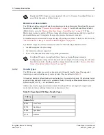
PowerSpan II becomes active as a PB slave when one of the following conditions occurs:
•
A processor bus master accesses a PCI resource, generating a memory or I/O space access
•
A processor bus master accesses a PCI resource, generating a configuration or IACK access
•
A processor bus master accesses PowerSpan II registers
This section covers the first two of these conditions. See
for a
discussion of the last two items in the bullet list above.
The operation of the PB Slave is described below by dividing the PB Slave transaction into the
following different phases:
•
Address phase: This section discusses the decoding of processor bus accesses.
•
Data transfer: This section describes control of transaction length.
•
Terminations: This section describes the terminations supported by PowerSpan II, and exception
handling.
Pull-up resistors are not required on the processor bus address (PB_A[0:31]) and data (PB_D[0:63])
signals to guarantee functional operation of PowerSpan II. However, adding resistors to the address and
data signals minimizes the current drawn by the PowerSpan II's tristated buffers when the bus is in an
idle condition. The system designer must decide whether to add these resistors to the address and data
bus.
The PowerSpan II PB Slave supports cacheable accesses to PCI, but it does not guarantee
coherency if more than one processor accesses a given range of memory. In order to address
this issue, operating system pages mapped to PowerSpan II must have the Memory
Coherency Attribute (M) set to zero. PowerSpan II performs PCI read prefetches. These reads
can be cached in an internal queueing memory within PowerSpan II — if PRKEEP is set to 1.
When a write is performed to a prefetched address, a subsequent read yields stale data.
Prefetching attributes for each image map must meet the systems cache coherency
requirements.


