5. I2C/EEPROM
128
PowerSpan II User Manual
80A1010_MA001_09
Integrated Device Technology
www.idt.com
5.2
Power-Up Configuration
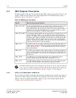
At the end of each PowerSpan II reset sequence, the I
2
C Interface initiates a sequential read with
device select code 0b1010000. If no response is detected, the read is terminated and the EEPROM
Load bit (ELOAD), in the
“Reset Control and Status Register” on page 324
(RST_CSR), is cleared to
indicate the absence of an external EEPROM.
When an EEPROM is not used in the system for initialization, the initialization occurs from the
processor bus. Once initialization is complete, the P1_LOCKOUT and P2_LOCKOUT bits must be
cleared in the
“Miscellaneous Control and Status Register” on page 318
(MISC_CSR) to enable the
host processor to assign memory space.
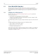
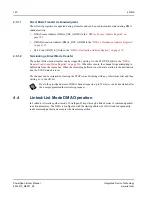
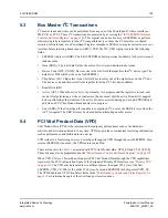
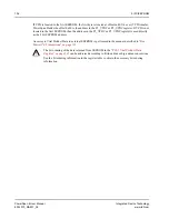
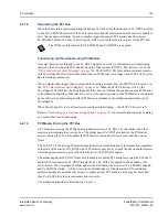
When a EEPROM is used in a system, the EEPROM device responds and a number of PowerSpan II
register bits are loaded from the external device and the ELOAD bit is set. During this loading process,
all accesses to PowerSpan II’s external interfaces are retried.
5.2.1
EEPROM Loading
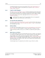
When the reset sequence is initiated by assertion of PO_RST_
—
a power-up reset
—
the register
loading process is defined by
. The first byte read from the EEPROM defines the loading
option and is reflected in the EEPROM Load Option (ELOAD_OPT) field, in the
Control and Status Register” on page 318
, at the conclusion of the loading process.
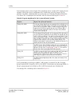
The loading options for EEPROM are short loading and long loading. The short load consists of 29
bytes and is designed to provide a PowerSpan II configuration to support the absence of a processor on
the PB Interface. The long load is 61 bytes in length and provides additional configuration
convenience. The upper 192 bytes of the EEPROM are reserved for PCI Vital Product Data (see
Vital Product Data (VPD)” on page 135
).
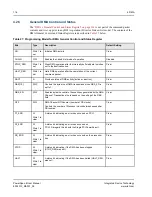
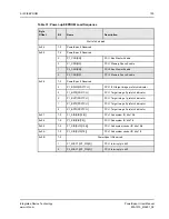
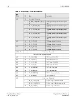
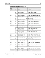
defines the power-up EEPROM load sequence. The shaded areas indicate registers not visible
in the Single PCI PowerSpan II.
assumes PCI little-endian bit ordering. Consult the register tables for each of the
registers listed in the table to obtain the corresponding PowerPC big-endian bit ordering.
Table 31: Power-up EEPROM Load Sequence
Byte
Offset
Bit
Name
Description
0x00
7-0
MISC_CSR[ELOAD_OPT]
0b00000001=short load
0b00000010=long load
0b00000100=reserved
others=do not load
0x01
7-0
PowerSpan II Reserved
0x02
7-0
PowerSpan II Reserved
0x03
7-0
PowerSpan II Reserved

