2. PCI Interface
81
PowerSpan II User Manual
80A1010_MA001_09
Integrated Device Technology
www.idt.com
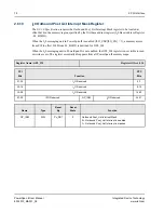
2.6.13
I2O Host Outbound Index Register
This register indicates the address in Host memory from which the Host is to retrieve the next
Outbound XMFA. This register is initialized by the IOP with an index received from the Host in an I
2
O
message. The register is written by the Host during I
2
O Outbound Option message passing.
When the I
2
O Host Outbound Index Register and the I
2
O IOP Outbound Index Register differ, the
Outbound Post List Interrupt Status bit is set in the OPL_IS register at offset 0x30 of the PCI I
2
O target
Image. When these registers contain the same Host memory address, the Interrupt is cleared.
This feature is only supported if the I
2
O Outbound Option is enabled with the XI2O_EN bit in the
I2O_CSR register and I2O_EN.
The HOPL_SIZE bit in the I2O_CSR register determines the alignment of this Index register.
The Register Offset is specified in the I
2
O Host Outbound Index Offset Register at offset 0x548 of the
PowerSpan II Register Map. The I
2
O Host Outbound Index Register must be located in the lower
4 Kbytes of the PCI I
2
O target image map.
When the I
2
0 Interface in PowerSpan II is not enabled, the HOST_OI register is not visible to read or
write access. The register essentially disappears from all PowerSpan II memory maps.
Register Name: HOST_OI
Register Offset: [HOST_OIO]
PCI
Bits
Function
PB
Bits
31-24
OI
0-7
23-16
OI
8-15
15-08
OI
16-23
07-00
OI
0
0
24-31
Name
Type
Reset
By
Reset
State
Function
OI[29:0]
R/W
Px_RST
0
Host Outbound Index


