2-19
2
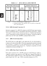
TABLE 2-4 4829A SIGNAL ASSIGNMENTS
Rear Panel Connector J2 Internal Connector J3
Pin #
Signals Signal Signals Pin #
DE-9P Direction
DE-9S
1
DCD
RD(B)
1
2
TxD
←
RD(A)
2
3
RxD
→
SD(A)
3
4
DTR +V
SD(B)
4
5
GND
−
GND
5
6
DSR
nc
6
7
RTS +V
nc
7
8
CTS
nc
8
9
nc
−
nc
9
Notes:
1. +V is + 9 Vdc through a 3.3 kohm resistor.
2. * Standard setting. TxD and RxD can be switched by setting
jumper W4 to the DTE position.
2.9.3.2 4829A Internal Connector J3
Internal connector J3 is a DE-9S connector with SD and RD differential signal
pairs. The SD and RD signal pairs are a four-wire, full-duplex interface.
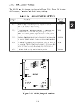
The SD and RD signal pairs can be jumpered together on the 4829A board
for half-duplex operation by installing jumpers W4 and W5.
2.9.4 4899A Serial Connections
The 4899A’s serial port is a DTE (Data Terminal Equipment) interface on a
DB-25S female connector. The connector has both RS-232 and RS-422/RS-
485 signals in accordance with EIA-STD - RS-530. RS-232 and RS-422
(RS-485) signal selection is made by setting jumpers inside the 4899A.
Refer to section 2.10 for jumper setting instructions. Table 2-2 shows the
4899A’s signal-pin assignments and signal directions.
Summary of Contents for 4809A
Page 5: ...ii This page left intentionally blank...
Page 51: ...2 30 2 This page left intentionally blank...
Page 89: ...4 8 4 This page intentionally left blank...
Page 99: ...5 10 5 This page left intentionally blank...
Page 125: ...A 26 A3 This page intentionally left blank...
Page 131: ...I Index 6 This page left intentionally blank...


