4-2
4
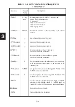
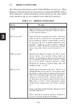
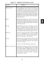
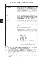
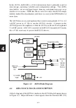
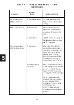
Figure 4-1 4899A Block Diagram
message packet includes the slave device address, the command number,
the registers and data (if any) that is being sent to the registers. A check-
sum is added to make up the complete Modbus RTU packet. The Modbus
packet is then placed in the serial transmit buffer. From the serial transmit
buffer, the data characters are sequentially placed in the microprocessor's
UART where they are serialized, passed through the selected serial driver
and outputted at the serial interface.
SCPI commands and IEEE-488.2 commands are parsed and used to set
control parameters, perform an operation or query a parameter. Responses
are placed in the GPIB buffer so they can be returned to the host controller
when the unit is next addressed to talk.
Incoming serial data from the Modbus slave device is received, converted
into TTL levels and applied to the UART's input. Each received character
is temporarily stored in the serial received data buffer. The characters in the
GPIB
CTLR
RAM
Microprocessor
Address
DCDR
µP BUS
+5
FLASH
Interface
to
internal
Serial
Device
Power
Supply
5-12 VDC
Input
+5V
Latch
GPIB
+5
Diagnostic LEDs
External
Serial
I/O
Summary of Contents for 4809A
Page 5: ...ii This page left intentionally blank...
Page 51: ...2 30 2 This page left intentionally blank...
Page 89: ...4 8 4 This page intentionally left blank...
Page 99: ...5 10 5 This page left intentionally blank...
Page 125: ...A 26 A3 This page intentionally left blank...
Page 131: ...I Index 6 This page left intentionally blank...

