3-7
3
enabling bits are set by writing the value equal to the sum of all of the
desired logic 1 bits to the enabling register. The value is normally decimal
but can be expressed in HEX, OCTAL or BINARY by prefixing the number
with a #H, #O or #B.
3.4.2 Event Status Register
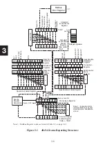
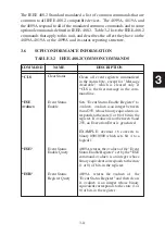
The Event Status Register reports events that are common to all 488.2 devices.
This includes events such as self test errors, command errors, execution
errors, power on and operation complete. ESR bits 2 through 6 light the
ERR LED when on. The Power-on event occurs at power turn-on and can
be used to signal a power off-on occurrence. In the 4899A, the Modbus
Error Register is summarized into the Event Status Register as Bit 6. The
488.2 Operation Complete event has no meaning for either unit.
TABLE 3-1 ESR BIT DEFINITIONS
Bit Bit Event Description
Weight
7 128
PON
The Power-on event occurs at power turn-on and can be used
to signal a power off-on occurrence.
6
64
Modbus Modbus Error detected. Reading the Modbus Errror Register
Error clears this bit. See the E? query in Table 3-5.
5
32
Cmd
Command Error
4.
16
Exc
Execution Error includes EDR not set and missing listen
handshake.
3
8
Flash Flash data corrupted.
2
4
Query Query error, data not read or read attempt with no data.
1
2
not used
0
1
OPC
Operation Complete has no meaning in the 48x9As.
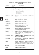
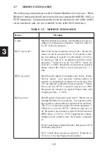
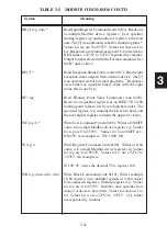
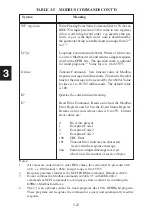
The Event Status Register is read with the
*ESR?
query. Use the
*ESE
commands to set the Event Status Enable Register as shown in the follow-
ing example:
*ESE 60
‘enables ESR error bits 2 through 5
*ESE 124
‘enables ESR error bits 2 through 6
*ESE?
‘queries the enabling register setting
3.4.3 Modbus Error Register
Summary of Contents for 4809A
Page 5: ...ii This page left intentionally blank...
Page 51: ...2 30 2 This page left intentionally blank...
Page 89: ...4 8 4 This page intentionally left blank...
Page 99: ...5 10 5 This page left intentionally blank...
Page 125: ...A 26 A3 This page intentionally left blank...
Page 131: ...I Index 6 This page left intentionally blank...


