2-2
2
2.3
INSTALLATION GUIDES
2.3.1 4899A Installation Guide
The following steps should be used as a guide to setting up and using your
4899A.
1. If the 4899A is to be used with RS-422 or RS-485 signals, change
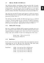
the jumper settings as directed in Section 2.11.
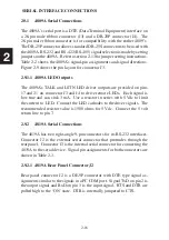
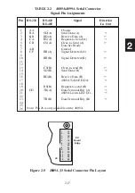
2. See Section 2.10 to select and/or design the serial cable.
CAUTION - Check 'standard' serial cable wiring carefully as may
standard cables may not make proper connections to the Modbus
RTU Controller.
3. If the unit is to go into a rack mounting kit, disconnect all cables
from the unit. Follow the instructions in Section 2.12 to install
the unit it in the rack mounting kit.
4. Connect the AC adapter to the 4899A and to the AC power. Turn
the unit on and verify that it passes its selftest and that it indicates
the correct GPIB address. Use the *IDN? query to verify GPIB
communication.
5. Review the factory settings in Table 1-1 to determine if your unit
needs to be reconfigured. If the 4899A needs to be reconfigured,
follow the instructions in Sections 2.4 - 2.8 to change its configura-
tion. Save the new settings.
6. Use a GPIB keyboard or similar interactive GPIB control program
to query the internal modbus device's model number or some other
known value following the examples in section 3.8. A typical
message would be 'R? 0,1' to query its model number. Read the
response to confirm that it is the expected response. Try out other
Modbus commands that apply to the Modbus device.
Summary of Contents for 4809A
Page 5: ...ii This page left intentionally blank...
Page 51: ...2 30 2 This page left intentionally blank...
Page 89: ...4 8 4 This page intentionally left blank...
Page 99: ...5 10 5 This page left intentionally blank...
Page 125: ...A 26 A3 This page intentionally left blank...
Page 131: ...I Index 6 This page left intentionally blank...


