2-27
2
2.11.4 4899A Jumper Settings
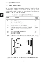
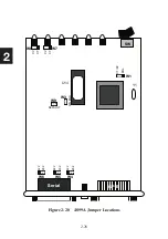
The 4899A has internal jumpers for selecting RS-232 and RS-422/RS-485
signals. Figure 2-19 on the next page shows the jumper locations on the
4899A’s PC board. Table 2-8 lists the jumper functions.
The jumpers are accessed by removing the two screws on the rear panel
and sliding the unit out from the rear of its case.
Jumpers W4, W5 and
W6 select the type of signals for the 4899A’s serial interface. For RS-232
serial signals, leave the jumpers in the ‘232’ position as shown in Figure
2-15. For RS-422 or RS-485 signals, set jumpers W4, W5 and W6 to the
‘422’ position. Do not change the other jumper positions.
Carefully slide the unit back into its case, fitting the PC board into the tracks
on each side of the case. Be sure the switch and LEDs are correctly aligned
before pushing the switch through the front panel.
Replace the two rear panel screws.
TABLE 2-8 4899A JUMPER SETTINGS
Jumper
Function
Factory
Setting
W1
Selects interrupt source
CT/CV
CT/CV for 4899A and 4895, PRL for 4892
W2
Set for EPROM size. Not user changeable
512
W3
Write Enable. Installed enables saving setup parameters
Installed
in EEPROM. Remove to block writes to configuration
tables
W4
RS-232/RS-422 signal selection Jumpers
232*
W5
232 for RS-232 signals
232*
W6
422 for RS-422 signals
232*
W7
LED signal jumpers
CV
W8
CV/PRL for 4899A, CT for 4895
CV
W9
Default Jumper. Restores factory default settings when
Open
installed. Same action as the CAL:DEFAULT command.
Notes: * Set RS485 to 1 for half-duplex operation or to 0 for full-duplex operation.
Summary of Contents for 4809A
Page 5: ...ii This page left intentionally blank...
Page 51: ...2 30 2 This page left intentionally blank...
Page 89: ...4 8 4 This page intentionally left blank...
Page 99: ...5 10 5 This page left intentionally blank...
Page 125: ...A 26 A3 This page intentionally left blank...
Page 131: ...I Index 6 This page left intentionally blank...


