3-4
3
3.3.1 Internal GPIB Address
The 4809A, 4819A and 4899A can be set to any unused GPIB primary ad-
dress between 0 and 30. The Bus Controller will use the primary address
to address the unit as a talker or as a listener. Bus addresses of 0 and 21 are
not recommend as these addresses are customarily used by Bus Controllers
as their own address.
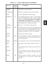
The internal GPIB address can be set or queried with the SCPI SYST:COMM:
GPIB:ADDR command. The change takes affect when the command is
executed so any subsequent commands will need to address the unit at its
new address. Use the IEEE-488.2 common command *SAV 0 to save the
new address value in the unit’s nonvolatile memory. Refer to Sections 2.6
and 2.7 for address setting instructions.
3.3.2 4809A Address External Address Switch
The 4809A’s GPIB address can also be set by connecting the 4809A to an
external address switch. Connector J2 contains the external address switch
input lines in addition to the GPIB bus signals. J2 mates to ICS’s GPIB
Connector/Address Switch Assemblies. These assemblies are small busi-
ness card size assemblies that make it easy to mount a GPIB connector and
an address switch on the rear panel of the host chassis.
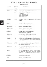
The 4809A’s external address switch is enabled with the SCPI SYST:COMM:
GPIB:ADDR:EXT ON command. When enabled, the 4809A reads the
external address switch at power turn-on. If the address switch is changed,
the unit must be powered off and back on before it will respond to the new
address. When the external address switch is enabled, the internal address
value is ignored.
3.4
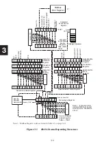
488.2 STATUS REPORTING STRUCTURE
Summary of Contents for 4809A
Page 5: ...ii This page left intentionally blank...
Page 51: ...2 30 2 This page left intentionally blank...
Page 89: ...4 8 4 This page intentionally left blank...
Page 99: ...5 10 5 This page left intentionally blank...
Page 125: ...A 26 A3 This page intentionally left blank...
Page 131: ...I Index 6 This page left intentionally blank...

