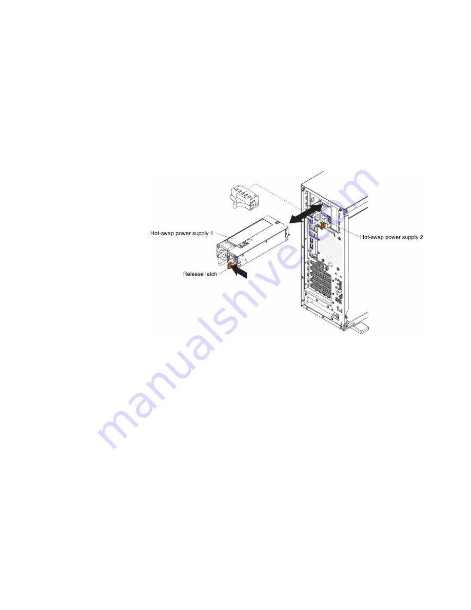
3.
Disconnect all external cables and power cords.
4.
Carefully turn the server on its side so that it is lying flat, with the cover
facing up.
Attention:
Do not allow the server to fall over.
5.
Remove the left-side cover (see “Removing the left-side cover” on page 39).
6.
Remove the existing hot-swap power supply (see“Removing a hot-swap
power supply” on page 398 ).
7.
Touch the static-protective package that contains the hot-swap power supply
to any unpainted metal surface on the server; then, remove the power supply
from the package and place it on a static-protective surface.
8.
Install the new hot-swap power supply and push it in until it locks into place.
Note:
v
If only one hot-swap power supply is installed in the server, a
power-supply filler must be installed in the empty power bay.
v
Do not mix power supplies with different wattage in the server.
9.
Route the power cord through the handle and cable tie if any, so that it does
not accidentally become unplugged.
10.
Connect one end of the power cord for the new power supply into the
connector on the back of the power supply; then, connect the other end of the
power cord to a properly grounded electrical outlet.
Note:
If the server has been turned off, you must wait approximately 3
minutes after you connect the server power cord to an electrical outlet before
the power-control button becomes active.
11.
Make sure that the ac power LED and the dc power LED on the ac power
supply are lit, indicating that the power supply is operating correctly. The two
green LEDs are to the right of the power-cord connector.
12.
If you are replacing a power supply with one of a different wattage, apply the
power information label provided with the new power supply over the
existing power information label on the server. Power supplies in the server
must be with the same power rating or wattage to ensure that the server will
operate correctly.
Chapter 6. Removing and replacing components
401
Summary of Contents for System x3300 M4
Page 1: ...System x3300 M4 Type 7382 Installation and Service Guide...
Page 2: ......
Page 3: ...System x3300 M4 Type 7382 Installation and Service Guide...
Page 8: ...vi System x3300 M4 Type 7382 Installation and Service Guide...
Page 18: ...xvi System x3300 M4 Type 7382 Installation and Service Guide...
Page 44: ...26 System x3300 M4 Type 7382 Installation and Service Guide...
Page 128: ...110 System x3300 M4 Type 7382 Installation and Service Guide...
Page 156: ...138 System x3300 M4 Type 7382 Installation and Service Guide...
Page 382: ...364 System x3300 M4 Type 7382 Installation and Service Guide...
Page 405: ...Chapter 6 Removing and replacing components 387...
Page 450: ...432 System x3300 M4 Type 7382 Installation and Service Guide...
Page 454: ...436 System x3300 M4 Type 7382 Installation and Service Guide...
Page 468: ...450 System x3300 M4 Type 7382 Installation and Service Guide...
Page 469: ......
Page 470: ...Part Number 00V9709 Printed in USA 1P P N 00V9709...


