6.
Touch the static-protective package that contains the DIMM to any unpainted
metal surface on the outside of the server. Then, remove the DIMM from the
package.
7.
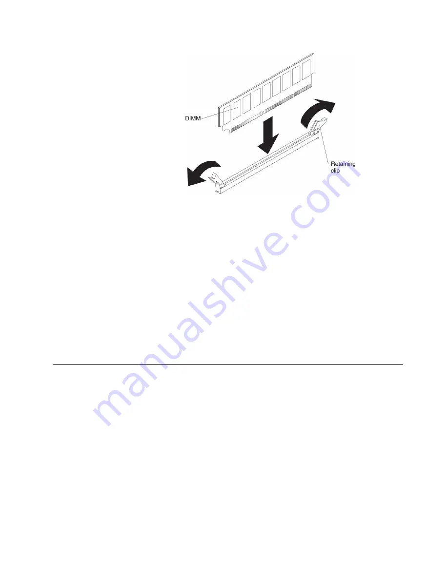
Turn the DIMM so that the DIMM keys align correctly with the connector.
8.
Insert the DIMM into the connector by aligning the edges of the DIMM with
the slots at the ends of the DIMM connector (see “System-board internal
connectors” on page 29 for the locations of the DIMM connectors).
9.
Firmly press the DIMM straight down into the connector by applying pressure
on both ends of the DIMM simultaneously. The retaining clips snap into the
locked position when the DIMM is firmly seated in the connector.
Note:
If there is a gap between the DIMM and the retaining clips, the DIMM
has not been correctly inserted; open the retaining clips, remove the DIMM,
and then reinsert it.
If you have other devices to install or remove, do so now. Otherwise, go to
“Completing the installation” on page 104.
Installing drives
The followings are illustrations of the server and the location of the drive bays.
Your hardware might differ, depending on the model.
Note:
If the server is configured for RAID operation using a ServeRAID adapter,
you might have to reconfigure your disk arrays after you install drives. See the
ServeRAID adapter documentation for additional information about RAID
operation and complete instructions for using the ServeRAID adapter.
The following illustrations show the location of the drive bays in the 2.5-inch and
3.5-inch hard disk drive server models.
v
The server with eight 2.5-inch hard disk drives:
Chapter 2. Installing optional devices
67
Summary of Contents for System x3300 M4
Page 1: ...System x3300 M4 Type 7382 Installation and Service Guide...
Page 2: ......
Page 3: ...System x3300 M4 Type 7382 Installation and Service Guide...
Page 8: ...vi System x3300 M4 Type 7382 Installation and Service Guide...
Page 18: ...xvi System x3300 M4 Type 7382 Installation and Service Guide...
Page 44: ...26 System x3300 M4 Type 7382 Installation and Service Guide...
Page 128: ...110 System x3300 M4 Type 7382 Installation and Service Guide...
Page 156: ...138 System x3300 M4 Type 7382 Installation and Service Guide...
Page 382: ...364 System x3300 M4 Type 7382 Installation and Service Guide...
Page 405: ...Chapter 6 Removing and replacing components 387...
Page 450: ...432 System x3300 M4 Type 7382 Installation and Service Guide...
Page 454: ...436 System x3300 M4 Type 7382 Installation and Service Guide...
Page 468: ...450 System x3300 M4 Type 7382 Installation and Service Guide...
Page 469: ......
Page 470: ...Part Number 00V9709 Printed in USA 1P P N 00V9709...


