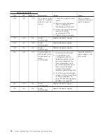
Table 4. System board jumpers (continued)
Jumper
number
Jumper name
Jumper setting
Note:
1.
If no jumper is present, the server responds as if the pins are set to 1 and 2.
2.
Changing the position of the UEFI boot recovery jumper from pins 1 and 2 to pins 2
and 3 before the server is turned on alters which flash ROM page is loaded. Do not
change the jumper pin position after the server is turned on. This can cause an
unpredictable problem.
3.
The physical presence requires manual setting on the server to change the TPM
configuration. The TPM is enabled and physical presence is not asserted by default. The
physical presence needs to be asserted to activate, deactivate, clear or change
ownership of the TPM.
Important:
1.
Before you change any switch settings or move any jumpers, turn off the
server; then, disconnect all power cords and external cables. Review the
information in Safety, “Installation guidelines” on page 36, “Handling
static-sensitive devices” on page 39, and “Turning off the server” on page 24.
2.
Any system-board switch or jumper blocks that are not shown in the
illustrations in this document are reserved.
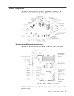
System-board LEDs
Any error LED can be lit after ac power has been removed from the system-board
tray so that you can isolate a problem. After ac power has been removed from the
system-board tray, power remains available to these LEDs for up to 90 seconds. To
view the error LEDs, press and hold the light path button on the system board to
light the error LEDs. The error LEDs that were lit while the system-board tray was
running will be lit again while the button is pressed. The following illustration
shows the LEDs and controls on the system board.
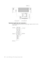
The following illustration shows the light-emitting diodes (LEDs) on the system
board.
Chapter 2. Installing optional devices
33
Summary of Contents for System x3300 M4
Page 1: ...System x3300 M4 Type 7382 Installation and Service Guide...
Page 2: ......
Page 3: ...System x3300 M4 Type 7382 Installation and Service Guide...
Page 8: ...vi System x3300 M4 Type 7382 Installation and Service Guide...
Page 18: ...xvi System x3300 M4 Type 7382 Installation and Service Guide...
Page 44: ...26 System x3300 M4 Type 7382 Installation and Service Guide...
Page 128: ...110 System x3300 M4 Type 7382 Installation and Service Guide...
Page 156: ...138 System x3300 M4 Type 7382 Installation and Service Guide...
Page 382: ...364 System x3300 M4 Type 7382 Installation and Service Guide...
Page 405: ...Chapter 6 Removing and replacing components 387...
Page 450: ...432 System x3300 M4 Type 7382 Installation and Service Guide...
Page 454: ...436 System x3300 M4 Type 7382 Installation and Service Guide...
Page 468: ...450 System x3300 M4 Type 7382 Installation and Service Guide...
Page 469: ......
Page 470: ...Part Number 00V9709 Printed in USA 1P P N 00V9709...

