Removal and Replacement
4-45
Memory Card, CPU Card, or I/O Card
Note: Refer to “Handling Static-Sensitive Devices” on page 4-14 before removing or
installing memory cards.
Note: Removing the memory card, CPU card, or I/O card requires using the extraction
tools. The extraction tools are stored on the left side of the front access plate.
Removal
1. Do the “CPU Module” removal procedure on page 4-39.
2. Remove the top cover:
– R30 and R40 CPU Enclosures: do the “Interlock Cable” removal procedure on page
4-43.
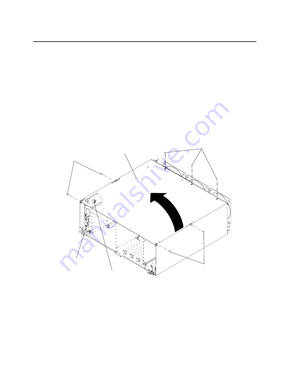
– R50 CPU Enclosure: remove the seven screws from the CPU module top cover, and
then remove the top cover.
Screws
Screws
Screws
CPU Module
Top Cover
Interlock Cable
Connector
Lateral Planar 1
Card
Summary of Contents for 7015-R30
Page 1: ...7015 Models R30 R40 and R50 CPU Enclosure Installation and Service Guide...
Page 10: ...x Service Guide...
Page 14: ...xiv Service Guide...
Page 34: ...1 20 Service Guide...
Page 214: ...6 10 Service Guide Detail 5 CPU Module 2 of 3 26 27 29 30 31 32 33 34 28 35...
Page 216: ...6 12 Service Guide Detail 6 CPU Module 3 of 3 36 37...
Page 252: ...B 8 Installation and Service Guide...
Page 288: ...Service Guide D 30...
Page 299: ......


