


CONTROL SYSTEM
TNV Application Manual
2-13
Minimum operating voltage
The minimum operating voltage of the E-ECU is 6.0 Vdc. Decreasing the E-ECU power supply voltage to
less than the above causes the E-ECU to reset.
When the battery voltage decreases to less than 6.0 V repeatedly at compression steps during cranking in
cold start conditions, for example, the engine may not be able to start. To avoid such a trouble, check the
battery and E-ECU power supply for correct voltage.
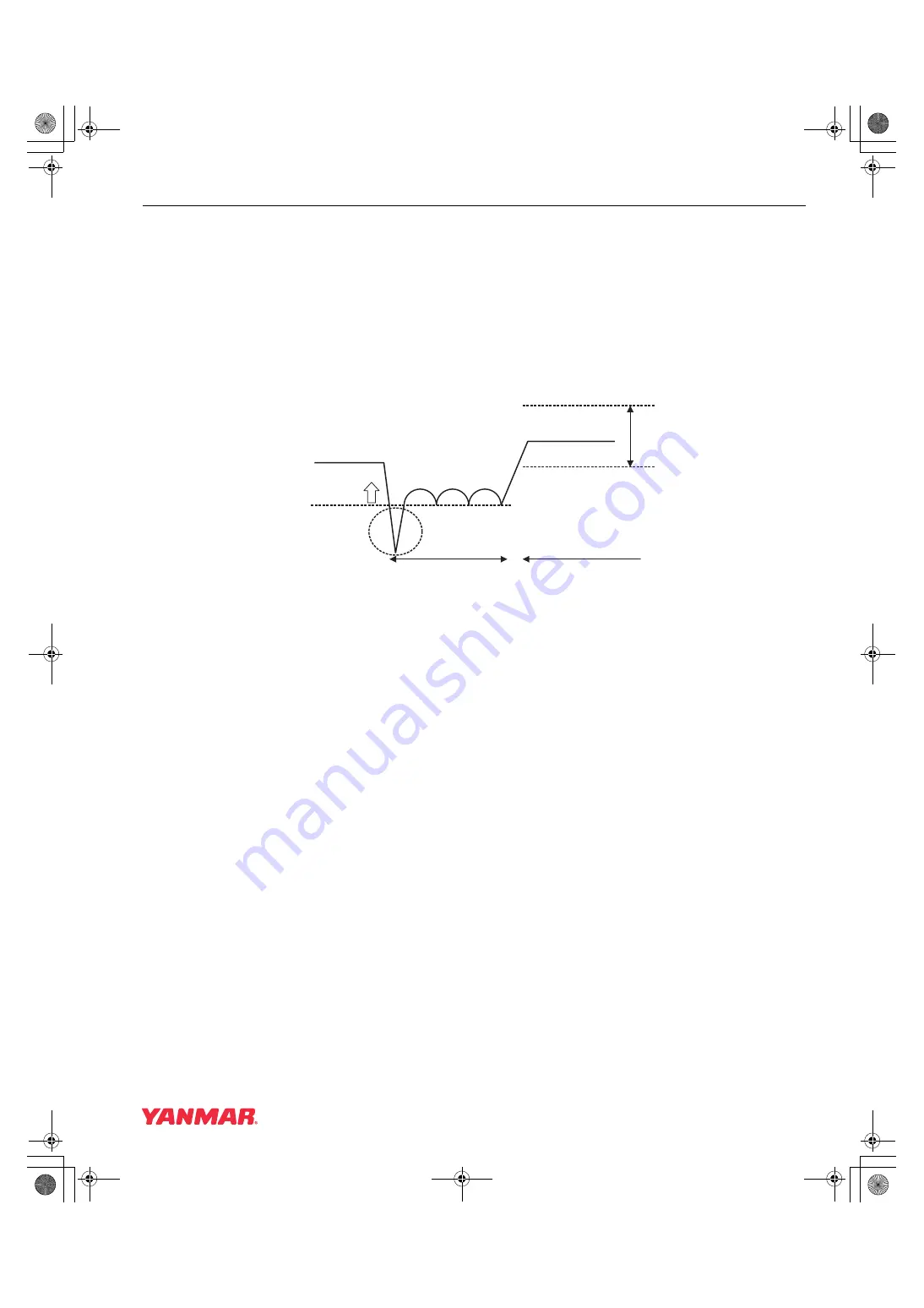
provides the transition of the E-ECU power supply voltage at engine start.
Figure 2-7
Transition of E-ECU power supply voltage at engine start
Minimum detectable speed
The E-ECU cannot detect speeds less than 100 min
-1
.
Number of start/stop cycles and duration of energization
The E-ECU saves engine logs in the internal EEPROM and updates them every time the power turns off if
the power self-holding feature (described later) is enabled, or at regular intervals if the power self-holding
feature is disabled. The design service life of the E-ECU is therefore dependent on the maximum number of
EEPROM write cycles.
The service life of EEPROM is limited to the order of 105 key-on operations if the power self-holding feature
is enabled, or 104 key-on duration hours if the power self-holding feature is disabled.
EEPROM is a nonvolatile storage; data stored in EEPROM is not lost if the E-ECU power turns off.
Safety features
The E-ECU has the following safety features:
• Two independent watchdog timers monitor the control software, and reset the microcomputer if detecting
a problem.
(1) The WDTs are supplied by the power supply IC to monitor the programs of the main and sub
microcomputers.
(2) The sub microcomputer monitors the program of the main microcomputer.
• If the sub microcomputer detects an overspeed condition of the engine, it turns off the rack actuator relay
to cut off the engine. (On overspeed condition occurs when the engine speed reaches High Idling Speed
plus 600 min
-1
by default).
• The power supply terminal (VB) of the E-ECU has a zener diode for protection against dump surge. As the
rack actuator and the rack position sensor must be protected by the zener diode, the power lines for these
components should be branched at a point as close to terminal VB as practicable.
more th
a
n 6.0V
10.0V
ECU
su
pply volt
a
ge (VB)
16.0V
cr
a
nking
OK
r
u
nning
00_Electronic_Control_System.book 13 ページ 2006年5月29日 月曜日 午後2時12分
Summary of Contents for Yanmar 3TNV82A-B
Page 95: ...CONTROL SYSTEM 2 76 TNV Application Manual 00_Electronic_Control_System book 76...
Page 96: ...Appendix Standard harness 1 00_ _E fm 1...
Page 97: ...Appendix Standard harness 2 00_ _E fm 2...
Page 98: ...TNV Series service tool Operation Manual...
Page 132: ...32 7 Main Menu Figure 7 15 Data Logging Data Monitor Screen...
Page 145: ...7 Main Menu 45 Figure 7 27 System Installation Configuration Screen...


