background image

UPS5000-H-1200 kVA 
User Manual (100 kVA Power Modules) 

5 Operations 


Issue 01 (2020-07-15) 

Copyright © Huawei Technologies Co., Ltd. 

144 


5.6 Testing Batteries 

5.6.1 Lead-Acid Battery Test 

5.6.1.1 Performing a Forced Equalized Charging Test 

Context 


Before performing a forced equalized charging test, ensure that: 


The mains input is normal. 


Batteries are properly connected. 


Batteries are not in equalized charging mode. 

Procedure 

Step 1


On the home screen of the LCD, choose 

System Info

 > 

Maintenance

 > 

Battery Maint.


Step 2


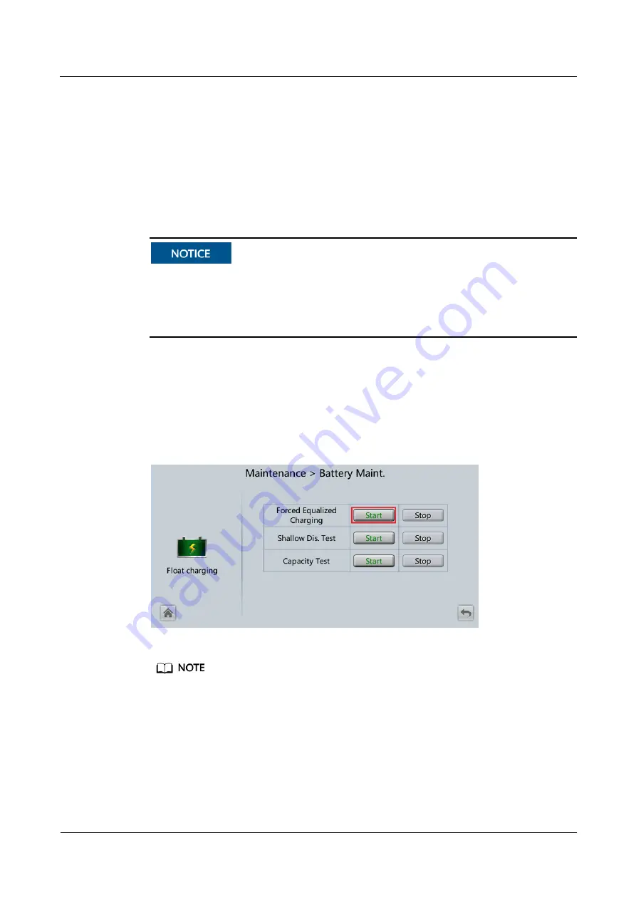
Tap 

Start

 on the right of 

Forced Equalized Charging

 to start a forced equalized charging 

test. 

Figure 5-9


Starting a forced equalized charging test 


The forced equalized charging test automatically stops in any of the following cases: 


The test duration reaches the forced equalized charging protection time (12–24 h, 18 h by default). 


The UPS generates a battery overtemperature, overvoltage, or overcurrent alarm. 


An alarm is generated. 

----End 

Summary of Contents for UPS5000-H-1200K-NT

Page 1: ...UPS5000 H 1200 kVA User Manual 100 kVA Power Modules Issue 01 Date 2020 07 15 HUAWEI TECHNOLOGIES CO LTD ...

Page 2: ...tomer All or part of the products services and features described in this document may not be within the purchase scope or the usage scope Unless otherwise specified in the contract all statements information and recommendations in this document are provided AS IS without warranties guarantees or representations of any kind either express or implied The information in this document is subject to c...

Page 3: ...eers Data configuration engineers Maintenance engineers Symbol Conventions The symbols that may be found in this document are defined as follows Symbol Description Indicates a hazard with a high level of risk which if not avoided will result in death or serious injury Indicates a hazard with a medium level of risk which if not avoided could result in death or serious injury Indicates a hazard with...

Page 4: ... Supplements the important information in the main text NOTE is used to address information not related to personal injury equipment damage and environment deterioration Change History Changes between document issues are cumulative The latest document issue contains all updates made in previous issues Issue 01 2020 07 15 This issue is the first release ...

Page 5: ...1 7 Battery Safety 11 1 8 Others 14 2 Overview 15 2 1 Model Description 15 2 2 Product Positioning and Features 15 2 2 1 Positioning 15 2 2 2 Highlights 16 2 2 3 Features 16 2 3 Application Scenarios 17 2 4 Working Principle 19 2 4 1 Conceptual Diagram 19 2 4 2 Working Modes 20 2 4 2 1 Normal Mode 20 2 4 2 2 Bypass Mode 21 2 4 2 3 Battery Mode 22 2 4 2 4 ECO Mode 23 2 4 2 5 Joint Power Mode 24 2 5...

Page 6: ...g Power Cables and Copper Bars 53 3 1 4 Unpacking 57 3 2 Single UPS Installation 58 3 2 1 Installing a Cabinet 59 3 2 1 1 Installation on the Floor 59 3 2 1 2 Channel Steel Installation 61 3 2 2 UPS Cable Connection Reference 62 3 2 3 Installing Cables and Copper Bars 63 3 2 4 Installing Optional Components 67 3 2 4 1 Installing the Top Air Flow Cabinet 67 3 2 4 2 Connecting Cables Between the UPS...

Page 7: ... 139 5 1 6 Optional Setting Parameters for the Top Air Flow Cabinet 139 5 2 Shutting Down and Powering Off the UPS 140 5 3 Cold Starting the UPS Using Batteries 141 5 4 Transferring to Bypass Mode Manually 142 5 5 Setting ECO Mode 142 5 6 Testing Batteries 144 5 6 1 Lead Acid Battery Test 144 5 6 1 1 Performing a Forced Equalized Charging Test 144 5 6 1 2 Performing a Shallow Discharge Test 145 5 ...

Page 8: ...al Maintenance 154 6 2 Lead Acid Battery Maintenance 155 6 2 1 Precautions for Battery Maintenance 155 6 2 2 Monthly Maintenance 155 6 2 3 Quarterly Maintenance 156 6 2 4 Annual Maintenance 157 7 Troubleshooting 158 8 Technical Specifications 160 A Optional TN C System Application 165 B Alarm List 166 C Acronyms and Abbreviations 177 ...

Page 9: ...ating or maintaining the equipment The safety instructions in this document are only supplements to local laws and regulations Huawei will not be liable for any consequences of the following circumstances Operation beyond the conditions specified in this document Installation or use in environments which are not specified in relevant international or national standards Unauthorized modifications t...

Page 10: ...uctor surface or terminal measure the contact point voltage and ensure that there is no risk of electric shock After installing the equipment remove idle packing materials such as cartons foam plastics and cable ties from the equipment area In the case of a fire immediately leave the building or the equipment area and turn on the fire alarm bell or make an emergency call Do not enter the building ...

Page 11: ...cratches cannot be exposed to an outdoor environment for a long period of time Before operations ensure that the equipment is firmly secured to the floor or other solid objects such as a wall or an installation rack Do not use water to clean electrical components inside or outside of a cabinet Do not change the structure or installation sequence of equipment without permission Do not touch a runni...

Page 12: ...lear of the sources and degree of various potential hazards in equipment installation operation maintenance Trained personnel personnel who are technically trained have required experience are aware of possible hazards on themselves in certain operations and are able to take protective measures to minimize the hazards on themselves and other people Operators operation personnel who may come in con...

Page 13: ... ensure that a distance of at least 30 mm exists between the cables and heat generating components or areas This prevents damage to the insulation layer of the cables Do not route cables behind the air intake and exhaust vents of the equipment Ensure that cables meet the VW 1 flame spread rating requirements Bind cables of the same type together When routing cables of different types ensure that t...

Page 14: ... Requirements To prevent fire due to high temperature ensure that the ventilation vents or heat dissipation system are not blocked when the equipment is running Install the equipment in an area far away from liquids Do not install it under areas prone to condensation such as under water pipes and air exhaust vents or areas prone to water leakage such as air conditioner vents ventilation vents or f...

Page 15: ... irrelevant personnel Carry the operation machinery and tools properly to prevent them from falling off and causing injuries Personnel involving working at heights are not allowed to throw objects from the height to the ground or vice versa Objects should be transported by tough slings hanging baskets highline trolleys or cranes Ensure that guard rails and warning signs are set at the edges and op...

Page 16: ...intact and confirm its load bearing capacity Do not overload it Ensure that the ladder is securely positioned The recommended angle for a ladder against the floor is 75 degrees as shown in the following figure An angle rule can be used to measure the angle Ensure that the wider end of the ladder is at the bottom or protective measures have been taken at the bottom to prevent the ladder from slidin...

Page 17: ...n moving heavy objects When moving the equipment by hand wear protective gloves to prevent injuries Move or lift the equipment by holding its handles or lower edges Do not hold the handles of modules such as power supply units fans and boards that are installed in the equipment because they cannot support the weight of the equipment Avoid scratching the cabinet surface or damaging cabinet componen...

Page 18: ...st and foreign matter from entering the UPS After unpacking batteries you are advised to connect the battery supply as soon as possible If you temporarily do not use the batteries store them in a dry and clean environment If batteries are stored for more than 90 days charge them in time Otherwise the battery lifespan may be affected Install the UPS in an area far away from liquids Do not install i...

Page 19: ...th only roofs railway station platforms gymnasiums and aquariums Environments that are conducive for the growth of microorganisms such as fungus or mildew Environments where rodents such as mice and insects exist 1 7 Battery Safety Basic Requirements Before operating batteries carefully read the safety precautions for battery handling and master the correct battery connection methods Do not expose...

Page 20: ...res extensive infrared radiation organic solvents and corrosive gases Take fire prevention measures Place and secure batteries horizontally Note the polarities when installing batteries Do not short circuit the positive and negative poles of the same battery or battery string Otherwise the battery may be short circuited Check battery connections periodically ensuring that all bolts are securely ti...

Page 21: ... safety precautions for lithium batteries are similar to those for lead acid batteries except that you also need to note the precautions described in this section There is a risk of explosion if a battery is replaced with an incorrect model A battery can be replaced only with a battery of the same or similar model recommended by the manufacturer When handling a lithium battery do not place it upsi...

Page 22: ...4 1 8 Others Exercise caution when manually shutting down the UPS inverter for transferring to bypass mode or when adjusting the UPS output voltage level or frequency Doing so may affect the power supply to equipment Exercise caution when setting battery parameters Incorrect settings will affect the power supply and battery lifespan ...

Page 23: ... capacity in full configuration 1200 kVA 4 Switch configuration N no switch 5 Cabling T Cables can only be routed in from the top 2 2 Product Positioning and Features 2 2 1 Positioning The UPS5000 H is a high end modular UPS launched by Huawei It adopts online double conversion and modular redundancy design for components Based on the digital signal processing DSP technology the UPS5000 H features...

Page 24: ...wer Density The power density of power modules can reach 100 kW 3 U which is the highest in the industry High Space Usage Space is efficiently used The UPS saves space for placing more IT equipment and reduces the footprint by 50 compared with traditional solutions of combining cabinets Easy Management and Monitoring The UPS is configured with an SNMP card which reduces the management cost and fea...

Page 25: ...5 This allows the UPS to connect to more loads and reduces customer investments Easy O M Power bypass and control modules are hot swappable A common engineer can finish maintenance within 5 minutes Smooth capacity expansion is supported The initial investment on the UPS is reduced and the UPS operating efficiency is improved The power supply and distribution status is monitored in real time Core p...

Page 26: ...ser Manual 100 kVA Power Modules 2 Overview Issue 01 2020 07 15 Copyright Huawei Technologies Co Ltd 18 Figure 2 2 Typical application scenario of a single UPS Figure 2 3 Typical application scenario of 1 1 parallel system ...

Page 27: ...an input mode indicates the energy flow direction 2 4 1 Conceptual Diagram The UPS is an online product It uses modular design which facilitates maintenance and capacity expansion The UPS uses the DSP technology for intelligent control The power module consists of a rectifier inverter and DC DC converter The UPS converts inputs into pure high quality sine wave outputs by using the high frequency s...

Page 28: ... Modes 2 4 2 1 Normal Mode In normal mode the rectifier converts AC power into DC power Then the inverter converts DC power into AC output At the same time the rectifier charges batteries over a charger The two conversions ensure high precision and high quality output voltages protecting loads from interferences such as input harmonics glitches and voltage transients ...

Page 29: ... power module experiences overtemperature overload or other faults that may shut down the inverter the UPS automatically transfers to bypass mode At the same time the rectifier is started and charges batteries over a charger In bypass mode loads are powered by the bypass module The bypass power supply is not protected by the UPS and therefore is prone to the mains outage abnormal AC voltage wavefo...

Page 30: ...i Technologies Co Ltd 22 Figure 2 7 UPS conceptual diagram in bypass mode 2 4 2 3 Battery Mode If the mains input is abnormal or the rectifier becomes abnormal the UPS transfers to battery mode The power module obtains DC power from batteries and the power is converted into AC output by the inverter ...

Page 31: ... on the LCD or web user interface WebUI In ECO mode when the bypass input is within the ECO voltage and frequency ranges and other ECO power supply conditions are met the UPS works in bypass mode and the inverter is in standby state When the bypass source voltage is outside the ECO voltage range the UPS transfers from bypass mode to inverter mode In bypass mode or inverter mode the rectifier keeps...

Page 32: ... required to ensure that the inverter is in standby state and the power flow has reached the inverter 2 4 2 5 Joint Power Mode If the UPS works properly and the AC input power of the rectifiers is insufficient the UPS transfers to joint power mode In this case the power module obtains energy from both the mains and batteries and the energy is converted into AC outputs over the inverter ...

Page 33: ...UPS5000 H 1200 kVA User Manual 100 kVA Power Modules 2 Overview Issue 01 2020 07 15 Copyright Huawei Technologies Co Ltd 25 Figure 2 10 Conceptual diagram in joint power mode ...

Page 34: ...UPS5000 H 1200 kVA User Manual 100 kVA Power Modules 2 Overview Issue 01 2020 07 15 Copyright Huawei Technologies Co Ltd 26 2 5 System Components 2 5 1 Appearance Figure 2 11 Appearance ...

Page 35: ...07 15 Copyright Huawei Technologies Co Ltd 27 2 5 2 Structure Figure 2 12 Structure with the door open 1 Surge protective devices SPDs and SPD switches 2 Power modules 3 Surge protection boxes 4 Control module 5 Intelligent detection card 6 Bypass control module 7 Bypass modules ...

Page 36: ...or description Indicator Color Status Description Running indicator Green Steady on The system is working in inverter mode Blinking at long intervals The inverter is ready and in standby state blinking at 0 5 Hz on for 1s and off for 1s The inverter is not started blinking at 0 2 Hz on for 2 5s and off for 2 5s Blinking at short intervals The module is not configured the inverter software and rect...

Page 37: ...g upgraded Fault indicator Red Steady on A critical alarm is generated for the inverter or rectifier Off There is no critical alarm for the inverter or rectifier or the software is being upgraded Functions The main power module consists of a power factor correction PFC rectifier and inverter It performs AC DC or DC DC conversion on the mains and battery inputs and stabilizes the bus voltage The in...

Page 38: ...ass control module Table 2 3 Indicator description Indicator Color Status Description Running indicator Green Steady on The system is working in bypass mode Blinking at long intervals The bypass has no output blinking at 0 2 Hz on for 2 5s and off for 2 5s Blinking at short intervals The bypass is not configured or the software is being upgraded blinking at 4 Hz on for 0 125s and off for 0 125s Of...

Page 39: ...e The power module overload times out In inverter mode both the active and standby energy control modules ECMs of the bypass unit are faulty The system runs abnormally The UPS is transferred to bypass mode manually Specifications Dimensions H x W x D Bypass module 263 5 mm x 642 mm x 668 mm Bypass control module 86 1 mm x 642 mm x 600 mm Weight Bypass module 90 kg Bypass control module 16 kg 2 5 5...

Page 40: ...icators for ECM 2 10 Dry contact card 11 Dry contacts 12 MDU port 13 RS485 port 14 Fast Ethernet FE port 15 COM2 port 16 COM1 port 17 Battery temperature sensor port 18 Optional card subrack cover Ports are protected by a security mechanism 2 5 5 2 ECM Appearance The control module consists of one active ECM and one standby ECM Figure 2 16 ECM Table 2 4 ECM functions Silk Screen Description PARALL...

Page 41: ...t it does not need to be replaced Off The ECM has no minor alarm or the software of the ECM is being upgraded FAULT Red Steady on The ECM has a critical alarm Off The ECM has no critical alarm or the software of the ECM is being upgraded Functions As a control interface for the entire system the ECM communicates with each module and provides a bus for communication between the dry contact card and...

Page 42: ...ted DC voltage and current are 24 V DC and 0 6 A and the maximum values are 30 V DC and 1 0 A The rated AC voltage and current are 24 V AC and 0 6 A and the maximum values are 30 V AC and 1 0 A During cable connection ensure that the voltage and current do not exceed these maximum values Table 2 6 Functions of control signal ports on the dry contact card Silk Screen Signal Description Status Descr...

Page 43: ... controlling BCB trip When the voltage is 12 V the BCB trips 0 V BCB not tripped 12 V BCB tripped 0 V BCB_0V Port for signal ground EPO_NO If the normally open NO port is connected to the EPO_12V port emergency power off EPO is triggered Closing the EPO port triggers EPO Open EPO_12V 12 V EPO_NC If the normally closed NC port is disconnected from the EPO_12V port EPO is triggered Opening the EPO p...

Page 44: ...put AC SPD fails Closed 0V Port for signal ground A dry contact card port takes effect only after you set it in the software You need to disable unused dry contact signals Set the EPO port to NO or NC as required If multiple UPSs are connected in parallel connect all used dry contact signals to each UPS Signal cables must be double insulated twisted cables If the cable length is within 25 50 m the...

Page 45: ...des the ambient temperature and humidity sensor port iBattery port FE port battery temperature monitoring port and network management port The MDU monitors the UPS allows users to set parameters delivers commands reports system information and displays key UPS information and parameters on the LCD Figure 2 19 Monitoring interface card DO_1 to DO_4 meet the maximum voltage and current requirements ...

Page 46: ... 2 COM2 Supported protocol Modbus RTU Connects to a southbound device such as an iBattery Network port FE Supported protocols Modbus TCP HTTPS and SNMP Connects to the network port on a PC Network port for connecting to the web service and for SNMP networking Northbound communications port RS485 Supported protocol Modbus RTU Connects to a northbound network management device or third party network...

Page 47: ...A Power Modules 2 Overview Issue 01 2020 07 15 Copyright Huawei Technologies Co Ltd 39 Figure 2 21 Wiring method 2 Figure 2 22 COM1 port pins Table 2 8 Pin definitions for the COM1 port Pin Description 1 GND 2 3 RS485 4 RS485 5 6 12V_PORT ...

Page 48: ...odules 2 Overview Issue 01 2020 07 15 Copyright Huawei Technologies Co Ltd 40 Figure 2 23 COM2 port pins Table 2 9 Pin definitions for the COM2 port Pin Description 1 RS485 2 RS485 3 4 RS485 5 RS485 6 GND 7 CANH0 8 CANL0 Figure 2 24 RS485 port pins ...

Page 49: ...nect pin 1 and pin 2 Pin 1 connects to RS485 and pin 2 connects to RS485 Connect pin 4 and pin 5 Pin 4 connects to RS485 and pin 5 connects to RS485 Connect pins 1 2 4 and 5 Twist cables to pin 1 and pin 4 into one cable and then connect it to RS485 Twist cables to pin 2 and pin 5 into one and then connect it to RS485 2 5 6 Intelligent Detection Card Appearance Figure 2 25 Intelligent detection ca...

Page 50: ...lled by the CPU Off Indicates that the intelligent detection card is powered off RUN Green Blinking at 0 5 Hz The intelligent detection board is running properly Blinking at 4 Hz The communication is interrupted ALM Red Steady on An alarm is generated Off No alarm is generated Signal cables must be double insulated twisted cables If the cable length is within 25 50 m the cross sectional area must ...

Page 51: ...ns Table 2 14 Pin definitions for the FE_1 port Pin Description 1 FE4_TX 2 FE4_TX 3 FE4_RX 4 5 6 FE4_RX 7 8 Functions In the integrated UPS solution the intelligent detection card detects the temperatures of the copper bars switches and environments of the battery bypass input mains input output bypass input of the switch cabinet mains input of the switch cabinet and output of the switch ...

Page 52: ...h 2 5 7 MDU Appearance Figure 2 28 MDU 1 Status indicator 2 LCD touchscreen Table 2 15 Indicator status Status Color Meaning On Red A critical alarm has been generated and the buzzer sounds continuously Yellow A minor alarm has been generated and the buzzer buzzes intermittently at 2 Hz Green The UPS is running properly or a warning has been generated Off The MDU is powered off The indicator on th...

Page 53: ...n the initial startup password during deployment View or obtain UPS running information during inspection NOTE Only Huawei service engineers or authorized service engineers are allowed to use the WiFi module To ensure security remove the WiFi module immediately after use Insert a USB flash drive to import and export configuration files export run logs and upgrade software 8 SD Reserved 9 DIP switc...

Page 54: ...high reliability In addition to advantages of common parallel systems the dual bus system is free from bottleneck failures but its configuration is complex 2 6 1 Single UPS This series uses a modular design in which multiple power modules are connected in parallel to deliver a high loading capacity If a single power module is faulty the other power modules continue working When the load power is s...

Page 55: ...dependent 1 2 MW systems Each 1 2 MW system consists of one or two 1 2 MW UPSs One of the two UPS systems is a master system and the other is a slave system The dual bus system is highly reliable and is suitable for loads with multiple input terminals You can install an optional static transfer switch STS to start a bus synchronization controller BSC provided in standard configuration The UPS syst...

Page 56: ...nd the UPS and supports overload protection short circuit protection and remote trip control Dry contact extended card Provides extended monitoring ports five relay output ports and five input ports Backfeed protection card Detects mains and bypass backfeed and provides protection ECM extended subrack Installed when the UPS is equipped with a backfeed protection card and dry contact extended card ...

Page 57: ... 60 m Transmits bus synchronization signals in a dual bus system Parallel cable 5 m 10 m 15 m Connects UPSs in parallel Top air flow cabinet Applies to the top air flow scenario The fan speed can be adjusted The ECM extended subrack does not support onsite installation If you require this optional component inform Huawei when you purchase the UPS so that Huawei can install the subrack before deliv...

Page 58: ...S away from water sources heat sources and flammable or explosive materials Keep the UPS away from direct sunlight dust volatile gases corrosive materials and air dense with salt particles Do not install the UPS in environments with conductive metal scraps in the air The optimal operating temperatures for valve regulated lead acid batteries VRLA batteries are 20 30 C Operating temperatures higher ...

Page 59: ...a clearance of at least 500 mm from the top of the cabinet for operations Reserve a clearance of at least 500 mm from the rear of the cabinet for ventilation Reserve a clearance of at least 800 mm if you need to perform operations at the rear of the cabinet If the top air flow cabinet is configured no space is reserved at the rear 3 1 2 Tools and Instruments Insulate installation tools to prevent ...

Page 60: ...c drill Alloy hole saw Heat gun Diagonal pliers Crimping tools Wire stripper Electric hydraulic pliers Clamp meter Multimeter Cable tie Level instrument Polyvinyl chloride PVC insulation tape Cotton cloth Label Electrician s knife Electrostatic discharge ESD gloves Protective gloves Insulated gloves Insulation protective shoes Torque screwdriver Cable cutter Brush Flat head screwdriver 2 5 mm ...

Page 61: ...e connection For more dedicated tools required see the corresponding component manuals Prepare tools based on site requirements 3 1 3 Preparing Power Cables and Copper Bars The UPS can generate large leakage currents A circuit breaker equipped with a residual current device RCD is not recommended Copper bars need to be prepared for the mains input bypass input and output and cannot be directly con...

Page 62: ...o Ltd 54 Figure 3 2 Top view of the distance between copper bars on the top unit mm 1 The areas marked by the line boxes are the recommended areas for installing connector boxes 2 The area marked by the line box is reserved for the dense busway Figure 3 3 Front view of the distance between copper bars on the top unit mm ...

Page 63: ...tery discharge current 3185A Recommended cable cross sectional area 6 x 2 x 240 mm2 PE 240 mm2 Battery input SmartLi Nominal battery discharge current 2467 A Maximum battery discharge current 3096 A Recommended cable cross sectional area For details see the IEC 60364 5 52 specifications and SmartLi User Manual Equipotential ground point Recommended cable cross sectional area 16 mm2 The rated volta...

Page 64: ... power source configure mains input power cables as input power cables In addition cables recommended in the table apply only when the following requirements are met Routing mode The cables are routed over a tray or bracket in a single layer E in IEC 60364 5 52 The distance between cables should be greater than twice the cable diameter Routing mode The cables are routed over a tray or bracket in a...

Page 65: ...me Specificationsa Mains input circuit breaker 2500 A 3P Bypass input circuit breaker 2500 A 3P Output circuit breaker 2500 A 3P a recommended model when the short circuit current where the circuit breaker is located is less than 65 kA The input circuit breakers recommended are for reference only If multiple loads are connected use recommended specifications for branch circuit breakers The circuit...

Page 66: ...king If the UPS installation environment is in poor condition and the UPS needs to be stored for a long time after it is unpacked take measures to prevent dust It is recommended that the UPS be wrapped with the original plastic coat Procedure Step 1 Use a pallet truck to transport the UPS to the installation position Step 2 Remove the UPS outer packing Step 3 After confirming that the UPS is intac...

Page 67: ...ure that the installation floor is flat Procedure Step 1 Determine the cabinet installation positions on the floor based on the holes in the marking off template for floor installation A mounting holes on the channel steel B mounting holes on the floor Figure 3 6 Hole dimensions unit mm Step 2 Use a hammer drill to drill holes for installing expansion bolts and then install expansion sleeves in th...

Page 68: ...s The expansion sleeves must be completely buried under the ground to facilitate subsequent installation Figure 3 8 Installing an expansion bolt unit mm 1 Drill a hole into the concrete floor using a hammer drill The hole depth ranges from 52 mm to 60 mm 2 Partially tighten the expansion bolt and vertically insert it into the hole Knock the expansion bolt using a rubber mallet until the expansion ...

Page 69: ...ets to the expansion bolt mounting holes on the floor Step 4 Install anchor baffle plates Figure 3 9 Installing anchor baffle plates End 3 2 1 2 Channel Steel Installation Prerequisites Huawei does not provide channel steel or expansion bolts used for securing channel steel Ensure that the surface of channel steels is smooth Figure 3 10 Recommended channel steel dimensions unit mm ...

Page 70: ...ates Figure 3 11 Installing anchor baffle plates End 3 2 2 UPS Cable Connection Reference Context Keep away from cabinets when preparing cables to prevent cable scraps from entering the cabinets Cable scraps may cause ignition during power on and result in personal injury and device damage After installing cables clean the cabinet top bottom copper bar wiring positions and other positions Ensure t...

Page 71: ...ked cable out of the cabinet cut the cable from the marked position strip the cable and crimp a terminal Figure 3 12 Preparing a cable terminal outside the cabinet Choose an appropriate cabling route based on the actual situation The figure is for reference only Step 4 Connect the cable with a crimped terminal to the corresponding copper bar Step 5 Clean foreign matter inside the cabinet End 3 2 3...

Page 72: ...e Step 1 Connect the equipotential ground point and the ground bar in the equipment room Figure 3 14 Connecting the equipotential ground point 1 Ground bar in the equipment room Step 2 Optional Remove the copper bars between the mains input and bypass input Perform this step only when the mains input and bypass input use different power sources 1 Remove the covers ...

Page 73: ...t Huawei Technologies Co Ltd 65 Figure 3 15 Removing the covers 2 Remove the screws that secure the guide rail of the SPD 3 Place the SPD on the horizontal plate without removing the cables 4 Remove the copper bars 5 Reinstall the SPD Figure 3 16 Removing copper bars Step 3 Install battery cables ...

Page 74: ...Installing battery cables 1 Connect the ground cable of the battery string or its BBB box to the battery PE of the UPS or the ground bar in the equipment room based on the site survey Step 4 Install top supports and covers of the battery terminal protective covers Figure 3 18 Installing top supports and covers Step 5 Connect input and output busbars based on the top copper bar position diagram ...

Page 75: ... Torque Mains input bypass input output PE Crimped DT terminals M12 45 mm 47 N m Step 6 Prepare and install a power distribution unit based on site requirements For details about the hole dimensions see Figure 3 2 Step 7 Install a signal cable Figure 3 19 Installing a signal cable End 3 2 4 Installing Optional Components 3 2 4 1 Installing the Top Air Flow Cabinet Install the top air flow cabinet ...

Page 76: ...UPS5000 H 1200 kVA User Manual 100 kVA Power Modules 3 Installation Issue 01 2020 07 15 Copyright Huawei Technologies Co Ltd 68 Appearance Figure 3 20 Appearance 1 Top air flow cabinet 2 UPS ...

Page 77: ...e 3 21 Top air flow cabinet structure 1 Fan power switch 2 Cover stopper 3 Cover Installing Cabinets Step 1 Determine the positions for installing cabinets on the mounting surface based on holes in the marking off template A mounting holes on the channel steel B mounting holes on the floor Figure 3 22 Fan unit hole dimensions unit mm ...

Page 78: ... to drill holes for installing expansion bolts and then install expansion sleeves in the holes Step 3 Remove the left panel and front panels from the UPS cabinets Step 4 Install the accessories of the top air flow cabinet 1 Remove the rear door panels from the UPS cabinets 2 Secure the PC panel to the inner side of the rear door panel from the outer side of the rear door using plastic rivets ...

Page 79: ...Issue 01 2020 07 15 Copyright Huawei Technologies Co Ltd 71 Figure 3 24 Securing the PC panel 3 Remove the door sills from the rear of the UPS cabinets Figure 3 25 Removing door header sills rear view of the cabinets 4 Install the accessories of the top air flow cabinet ...

Page 80: ...w of the cabinets 5 Reinstall the door sills and rear door panels 6 Install anchor baffle plates at the rear of each cabinet Figure 3 27 Installing anchor baffle plates at the rear of each cabinet 1 Top air flow cabinet 2 UPS cabinets Step 5 Secure the cabinets 1 Use M12x60 expansion bolts to secure the UPS cabinets to the expansion bolt mounting holes on the floor Figure 3 28 Securing UPS cabinet...

Page 81: ...flow cabinet c Tighten the anchor bolts d Reinstall the bottom cover Figure 3 29 Combining the top air flow cabinet with the UPS Step 6 Install the removed side panel on the side of the top air flow cabinet Step 7 Install anchor baffle plates on the side and front of each cabinet Step 8 Install the cables 1 Remove an accessory cover from the top of the top air flow cabinet 2 Connect the power cabl...

Page 82: ...chnologies Co Ltd 74 Figure 3 30 Power supply to the top air flow cabinet End Replacing Fans If a fan is faulty perform the following steps to replace it Step 1 Switch off the circuit breaker remove the cover stoppers and remove the covers Figure 3 31 Removing covers Step 2 Remove the cables and fan assembly ...

Page 83: ...ssembly Step 3 Remove the fan 1 Remove the fan cover 2 Remove the terminal of the fan signal cable 3 Remove the fan power cable and label it 4 Remove the faulty fan Figure 3 33 Removing the faulty fan Step 4 Install the new fan and install the fan power cable and signal cable Step 5 Reinstall the fan cover Step 6 Reinstall the fan assembly and install cables ...

Page 84: ...s If the SmartLi is configured perform the following steps to connect cables Procedure Step 1 Connect cables between the UPS and the SmartLi 1 Connect battery cables to each SmartLi 2 Connect the COM2 port on the monitoring interface card MUS05A in the control module to the COM port on the master SmartLi cabinet The number and colors of cables are for reference only Figure 3 34 Cable connection di...

Page 85: ...erations and cover the cable with protective tubing Triggering EPO will shut down the rectifier inverter charger and static bypass but does not disconnect the UPS mains input To power off the UPS completely open the front end input switch when triggering EPO Connect the requisite EPO switch to UPS dry contacts Figure 3 35 Cable connection for an NC EPO switch Figure 3 36 Cable connection for an NO...

Page 86: ...V When the EPO switch is turned on EPO is triggered 3 3 Parallel System Installation 3 3 1 Connecting Power Cables Procedure Step 1 Ground each UPS in a parallel system separately and connect power cables and battery cables Step 2 Choose a parallel mode and connect cables to the parallel system based on site requirements Figure 3 37 Conceptual diagram of a 1 1 parallel system Connect power cables ...

Page 87: ...am of a dual bus system The length and specifications of power cables on each UPS should be the same to achieve current equalization in bypass mode The power cables include bypass input power cables and UPS output power cables End 3 3 2 Connecting Signal Cables Connecting Signal Cables to a Parallel System Figures show only the CM which stands for the UPS ...

Page 88: ...lation Issue 01 2020 07 15 Copyright Huawei Technologies Co Ltd 80 Figure 3 39 Connecting signal cables in a 1 1 parallel system Figure 3 40 Connecting signal cables in a single UPS dual bus system Connecting Other Signal Cables Connect signal cables for each UPS ...

Page 89: ... of a busway and cable are labeled Labels are concise and easy to understand 05 Cable ties Cable ties are secured evenly and no burr exists 06 Cable and busbar connections The input busbar output busbar and battery cables are securely connected For the cables secured by screws the spring washers are flattened 07 Grounding The resistance between the UPS ground bar and the equipment room ground bar ...

Page 90: ... the rear module subrack 1 In the scenarios where holes are drilled or covers are removed for routing cables use sealing putty to fill in the gap between the cables and the cabinets after routing cables and checking cable connections 2 After verifying the installation reinstall all the covers 3 Do not remove the dustproof cover before power on to prevent dust from entering the cabinets ...

Page 91: ... this document correspond to the MDU version V500R021C00SPC100 and are for reference only 4 1 LCD Interface 4 1 1 Main Menu The LCD screen is divided into three parts status bar alarm bar and information area Figure 4 1 shows the default main menu Table 4 1 describes the functions of the areas on the menu Figure 4 1 Main menu Table 4 1 Main menu description No Area Function ...

Page 92: ...ms based on severity Tap the alarm icon to open the active alarm screen 3 Informatio n area Displays the current power flow and key information about loads and batteries Tap icons for Bypass Mains Battery and Load to view details Table 4 2 describes the functions of common buttons Table 4 2 Functions of common buttons Button Function Returns to the main menu Scrolls the page down Scrolls the page ...

Page 93: ... Ltd 85 Figure 4 2 System Info 4 1 2 1 Module Data On the System Info screen tap the UPS picture The Cabinet N Data screen is displayed Select a module to view its running data indicates the selected module as shown in Figure 4 3 Figure 4 3 Module data 4 1 2 2 Runn Info On System Info tap The Runn Info screen is displayed ...

Page 94: ...isplayed on the Runn Info screen If Current equalization detection in Monitoring Running Parameter Output Setting on the WebUI is set to Enable and the number of inverter modules is greater than or equal to 2 Mod Cur Eql Data is displayed on the Runn Info screen Table 4 3 AC Output Item Description Phase voltage V AC output phase voltage Line voltage V AC output line voltage Phase current A AC out...

Page 95: ...utput active power Hist max load rate Historical maximum load rate of each phase on the UPS Hist Max Active Power kW Historical maximum active power of each phase on the UPS Hist Max Apparent Power kVA Historical maximum apparent power of each phase on the UPS Table 4 5 Mains input Item Description Phase voltage V Mains input phase voltage Line voltage V Mains input line voltage Phase current A Ma...

Page 96: ...of the battery A battery sensor is required If no sensor is connected N A is displayed Backup time min Battery backup time estimated at the current load Remaining cap Remaining battery capacity SOH State of health Maximum Cell Temperature C only for lithium batteries Min Cell Temperature C only for lithium batteries Table 4 8 Total Runtime Item Description Bypass runtime h Total time during which ...

Page 97: ...tate of charge SOC and SOH of each battery string Battery System Battery String N displays the temperature voltage internal resistance current SOC and SOH of a single battery in the battery string Intelli Temp Detect displays the temperatures of the copper bars switches and environments of batteries bypass input mains input output bypass input of the switch cabinet mains input of the switch cabine...

Page 98: ...ritical alarm minor alarm or warning is generated Buzzer off If the buzzer is disabled the buzzer does not buzz If the buzzer is enabled Buzzer Off is displayed on the operation screen Twinkle When the UPS communicates with the northbound NMS the function determines the position of the UPS in the NMS layout diagram 4 1 2 4 Settings On System Info tap The Settings screen is displayed Figure 4 7 Set...

Page 99: ...gure 4 10 Comm Settings lithium battery Figure 4 11 IP Settings IP address allocation If the MDU is connected to a computer over a network cable the IP address can only be allocated manually The IP addresses of the MDU and computer must be on the same network segment and must be different If the MDU is connected to a computer over a LAN switch or router with the DHCP function the IP address can be...

Page 100: ...10110110 01100010 111000 01 01110000 Subnet mask 255 255 255 192 11111111 11111111 111111 11 11000000 11111111 11111111 111111 11 11000000 Bitwise AND operation result 10110110 01100010 111000 01 01000000 10110110 01100010 111000 01 01000000 Automatic The MDU automatically searches for available IP addresses in the connected network Ensure that the MDU and computer IP addresses are on the same net...

Page 101: ...nt conditions onsite 9600 9600 19200 115200 Parity mode Specifies the RS485 communication frame composition bit When device nodes use RS485 communication set the parity modes for the device nodes to the same mode None None Odd Even Stop bit Specifies the stop bit in the Modbus communication frame format When the UPS is connected over the serial port Modbus set this parameter based on the frame for...

Page 102: ...e Range ModbusTCP encryption If Modbus TCP is used for communication communication links do not implement encryption or implement encryption based on the selected encryption mode Enable Disable Enable Figure 4 14 Ambient temperature and humidity sensor Item Description Default Value Value Range Start address N A 32 32 44 Quantity Number of cascaded ambient temperature and humidity sensors 0 0 4 ...

Page 103: ...Ltd 95 Figure 4 15 Battery temperature sensor Item Description Default Value Value Range Start address N A 16 16 28 Quantity Number of cascaded battery temperature sensors 0 0 4 Figure 4 16 BMU Item Description Default Value Value Range Start address N A 112 N A Quantity Number of cascaded battery monitor units BMUs 0 0 12 ...

Page 104: ...ion set WiFi SSID after connecting a WiFi module over a USB port to identify the WiFi device to which the mobile phone is connected UPS_WIFI Last six characters of the MAC address N A Password The password for accessing WiFi Changeme N A Figure 4 18 Access control Item Description Default Value Value Range SSH Refers to a secure encrypted transmission protocol used to access the UPS with a termina...

Page 105: ...The Modbus TCP services are unavailable Read only Only the read permission is enabled Settings are not allowed NetEco The read permission and the write permission on related parameters supported by the NetEco are enabled Enable All functions are available Enable Disable Enable Read only NetEco SNMP Refers to the Simple Network Management Protocol used to connect to the NetEco Disable The SNMP serv...

Page 106: ...navailable Read only Only the read permission is enabled Settings are not allowed NetEco The read permission and the write permission on related parameters supported by the NetEco are enabled Enable All functions are available Figure 4 19 Battery System Item Description Default Value Value Range SmartLi start address SmartLi communication address when the UPS queries SmartLi data 80 N A ...

Page 107: ...r Modules 4 User Interface Issue 01 2020 07 15 Copyright Huawei Technologies Co Ltd 99 System Settings Figure 4 20 System Settings screen 1 Figure 4 21 System Settings screen 2 If lead acid batteries are used you can set Batt temp sensor B_TEMP ...

Page 108: ...working mode Normal mode Normal mode ECO Self load mode Converter mode ECO voltage range In ECO mode when the difference between the bypass voltage and the rated voltage is greater than the specified value the system determines that the ECO voltage is abnormal and transfers to inverter mode 5 5 6 7 8 9 10 BSC mode When Huawei UPSs form a dual bus system set this parameter to Standard BSC mode Afte...

Page 109: ...Disable Enable Air filter maintenance period d Specifies the rack air filter maintenance interval If you set this parameter to 0 there is no reminder 0 0 365 Intra rack power module startup delay s The two parameters enable the UPS to control the interval that each rack or module transfers from battery mode to normal mode which reduces the impact on the generator or power grid In the case of batte...

Page 110: ...e Runn Info screen Enable Disable Enable Switch cabinet Enable this parameter when a switch cabinet is installed After this parameter is set to Enable the running status of the switch cabinet can be detected Disable Disable Enable Top outlet cabinet Enable this parameter when a top air flow cabinet is installed Disable Disable Enable Bottom cable entry cabinet Enable this parameter when a bottom c...

Page 111: ... the generator Disable Disable Enable Input cur limiting ratio Allows the UPS to limit the input current to be lower than the ratio to protect the generator 200 50 200 Output Settings Figure 4 24 Output Settings screen Item Description Default Value Value Range Output voltage level V Specifies the system output voltage level This parameter can be set only after the inverter shuts down After you ch...

Page 112: ...ency is generally different from the bypass frequency when the bypass frequency changes If the output is overloaded or the inverter is faulty an interruption less than 20 ms occurs when the UPS transfers from inverter mode to bypass mode If the rate is fast the inverter frequency may be unstable 0 6 0 1 2 0 EOD restart The UPS transfers to battery mode when the mains is abnormal When batteries rea...

Page 113: ...20 or 25 The default value is 15 When the voltage level is 400 V the value is 10 15 or 20 The default value is 15 When the voltage level is 415 V the value is 10 or 15 The default value is 10 Minimum bypass voltage When the difference between the bypass voltage and the rated voltage is greater than the specified value the system determines that the bypass voltage is abnormal and the bypass is unav...

Page 114: ...correct estimated discharge time may cause a data backup failure When you set parameters ensure the following Dis curr 0 1C EOD Dis curr 0 3C EOD Dis curr 0 5C EOD Dis curr 1 0C EOD A cell consists of electrodes and electrolyte and is the basic unit of a battery Each cell has a nominal voltage of 2 V A battery is a module consisting of a single cell or multiple cells assembled in a shell Each batt...

Page 115: ...ed from the installation time comes N A N A Maintenance period d Specifies the interval for reminding users of battery maintenance 0 0 365 Cell float voltage V cell Specifies the battery float charging voltage 2 25 2 23 2 30 Cell equalized volt V cell Specifies the battery equalized charging voltage 2 35 2 30 2 40 Dis curr 0 1C EOD V cell Specifies the EOD threshold when the discharge current is 0...

Page 116: ...pecifies the charge voltage of lithium batteries the value is automatically obtained N A N A Chg cur limiting coef C Lithium battery You can set the charge current limit value The current limit coefficient is a multiple of the battery capacity 0 50 0 10 1 00 Lead acid battery You can set the charge current limit value The current limit coefficient is a multiple of the battery capacity 0 10 0 05 0 ...

Page 117: ...ommunication Specifies the communication address when the northbound device queries iBOX data 0 0 124 iBAT number of iBOXN Specifies the number of iBATs managed by the iBOX 0 0 300 Figure 4 30 Advanced Param Item Description Default Value Value Range Current source Specifies the specifications of the Hall effect sensor used to detect iBOX current Hall sensor 200A Hall sensor 200A Hall sensor 600A ...

Page 118: ... run properly When you disable a dry contact card the related dry contact signals are disabled Dry contact signals are displayed on the screen only when you enable the corresponding dry contact card When a dry contact card is not connected or some dry contacts of a dry contact card are not used disable the card or the unused dry contacts on the screen to prevent false alarms encloses a unit and en...

Page 119: ... is set to Enable the port has dry contact signal access How to use the port depends on the status of the BP SYSMT switch BP SYSMT switch function If the BP SYSMT switch is set to Enable this parameter is displayed on the screen Set this parameter to determine whether the port is used to detect the status of the PDC bypass input circuit breaker or system maintenance circuit breaker SPD SYSOUT swit...

Page 120: ...to the signal of the output dry contact DO on the MUE07A MUE07A DI_1 MUE07A DI_2 MUE07A DI_3 MUE07A DI_4 MUE07A DI_5 Corresponds to the signal of the input dry contact DI on the MUE07A User Settings Figure 4 32 User Settings screen Item Description Default Value Value Range Language Twelve languages are supported English English Chinese Spanish Dutch French German Italian Polish Portuguese Russian...

Page 121: ... string of six to eight digits If the password complexity check is set to Enable the password is required to be a string of 6 20 characters and contain at least two types of characters Set the date and time to the actual date and time Time Zone Figure 4 33 Time Zone settings Set the local time zone 4 1 2 5 Maintenance On System Info tap The Maintenance screen is displayed ...

Page 122: ...Settings Basic Param is not 0 iBOX Control is displayed on the Maintenance screen Battery Maint Perform battery maintenance when no alarm is generated on the UPS Otherwise power output may fail A proportion of battery capacity discharges during battery maintenance This reduces the discharge time before the next charge Do not perform battery maintenance when a generator is connected Battery mainten...

Page 123: ...ies forcibly Shallow Dis Test Allows you to partially discharge batteries A shallow discharge test is conducted to test the battery loop reliability and short time discharge capacity when the batteries have not been discharged for a long time Capacity Test Allows you to fully discharge batteries A deep discharge test is conducted to obtain the battery discharge performance data USB Operations You ...

Page 124: ...erted switchover is supported only after the ECM is configured and starts working properly about 30 seconds If an ECM to be maintained is still working perform ECM switchover a dialog box is displayed for you to confirm this operation After the switchover is complete ensure that the ECM to be maintained is in standby state that is the green indicator is blinking and then maintain it iBOX Control R...

Page 125: ...the selected iBAT in an iBOX NOTE The interval between two measurement operations must be greater than 10 minutes Bus Capacitor Life Estimate If the service life of a capacitor is about to end that is Module X bus capacitor life y is less than 1 0 contact Huawei technical support to replace the power module Wizard Startup The wizard startup can be used to test the bypass mains inverter inverter by...

Page 126: ... overcurrent alarm No generator is connected to the UPS The mains batteries charger and discharger are normal No overload alarm is generated The SOC is greater than 30 Figure 4 39 Wizard Startup Choose Settings Dry Contact Set set MUE05A connection to Enable and set BCB connection OL to Enable Wizard Startup can be used to test the battery switch tripping function 4 1 2 6 About On System Info tap ...

Page 127: ...r Modules 4 User Interface Issue 01 2020 07 15 Copyright Huawei Technologies Co Ltd 119 Figure 4 40 About screen 4 1 3 System Status On the System Status to view the mains input bypass input load and battery information Figure 4 41 System status ...

Page 128: ... 4 42 Common functions 1 Figure 4 43 Common functions 2 4 2 WebUI 4 2 1 Login Context Internet Explorer 11 is used as the example browser The system supports Internet Explorer 11 and Firefox 31 0 Procedure Step 1 Open the browser and choose Tools Internet Options Step 2 On the Advanced tab page ensure that Use TLS 1 0 and Use TLS 1 1 are selected and click OK ...

Page 129: ...55 Table 4 11 User description Default User Preset Password User Rights admin system administrator Changeme Performs all operations on the LCD and WebUI including system running information browsing system information exporting parameter setting system control system configuration and system maintenance operator common user Changeme Only browses the system running information exports system inform...

Page 130: ...ser logs in to the WebUI if another user logs in with the same user name the current account will be logged out It is advised to change the password after the first login using User Mgmt on the Config page to prevent unauthorized access End 4 2 2 Home Figure 4 45 Home Item Description System Overview View the operation status of the mains input bypass input battery and AC output of the system Acti...

Page 131: ...ummary NOTE If Number of iBOXs is not 0 and lead acid batteries are used Battery String Summary is displayed on the Monitoring page Set parameters for the iBOX and iBAT connected to each battery string UPS System Table 4 12 System settings Item Description Default Value Value Range High ambient temperature alarm threshold C An alarm is generated when the ambient temperature reaches or exceeds the ...

Page 132: ... the ECO function is enabled If this parameter is set to Disable the system is not allowed to enter ECO mode when the DG supplies power to the bypass Enable Disable Enable RAM verification Specifies whether to enable the memory check function If this parameter is set to Enable the control chip RAM working status is checked regularly If this parameter is set to Disable regular check is disabled Dis...

Page 133: ...ally This function can be used only when the UPS carries no load Disable Disable Enable Output interruption transfer time ms Set this parameter based on the output interruption time acceptable to loads 0 0 40 60 80 100 120 Max BPM transfer times Cross currents occur during the transfer between bypass mode and inverter mode which impacts the system This parameter limits the number of transfers betw...

Page 134: ... and the rectifier and inverter automatically start when the bus voltage recovers less than 420 V within Bus overvolt recovery time 5s 5s 1min 5min 10min Capacitor failure detection If this parameter is set to Enable the inverter capacitor fault detection is performed based on the settings of Capacitor failure detection upper limit and Capacitor failure detection lower limit If the inverter capaci...

Page 135: ... temp comp center C Specifies the reference temperature during float charging voltage temperature compensation 25 20 30 Automatic equalized charging If this parameter is set to Enable the UPS automatically changes the battery management status to equalized charging based on the charge current and float charging time Enable Disable Enable Transfer to equalized charging curr coef C10 Batteries enter...

Page 136: ...t dis voltage deviation alarm thres 20 10 30 Batt charging capacity mismatch After this function is set to Enable default value an alarm is generated if the configured battery capacity exceeds the charging capacity of the rack Disable Disable Enable Batt mode shut When the mains fails and the UPS transfers to battery mode the UPS can automatically power off according to the preset shutdown delay t...

Page 137: ...ge is lower than this threshold the output dry contact generates a signal 1 70 1 70 2 10 Lithium battery If Batt Volt Below Threshold is set for an output dry contact and the minimum electrochemical cell voltage is lower than the threshold the output dry contact generates a signal 2 80 2 60 3 20 Battery String Summary Item Description No of iBOX Number of an iBOX connected to the UPS iBAT start No...

Page 138: ...e Data Queries the performance data of the components related to the system Export Data Export Historical Alarm Active Alarm Operation Log and Performance Data 4 2 5 System Settings Figure 4 48 System settings lead acid battery Figure 4 49 System settings lithium battery Site Configuration Table 4 16 System type Item Description Name Site name Location Site location ...

Page 139: ...ate file Export the root certificate Time Set the time zone and time for the site Comm Settings Set parameters such as IP Settings RS485 Settings ModbusTCP Settings Amb T H Sensor ModbusTCP Table 4 18 Access ModbusTCP security certificate Item Description Upload CA certificate file Import a CA certificate for the UPS to verify the certificate of the Modbus TCP communication access party Upload loc...

Page 140: ... same as that on the NMS If SNMP Trap is incorrectly set or not set system information will be lost or not reported in time Event Notice Mailbox Settings Set the email address of the recipient in Mailbox Settings Alarm Notification Set Alarm notification delay in Alarm Notification Parameter Settings set Time of the first reminder and Interval in Alarm Reminder Configuration and perform the Add Mo...

Page 141: ...query and export E label export Fault Information and import and back up Configuration File Figure 4 50 Maintenance page Item Description Software Upgrade Upgrades the software version of the system Version Information Queries the software and hardware versions of devices in the system Configuration File Imports and exports system configuration files E label Queries and exports e labels of devices...

Page 142: ...S Context The following operations are applicable to a single UPS For parallel systems contact Huawei technical support Before power on ensure that the devices have passed all check items in the section Verifying the Installation Before power on ensure that all the UPS switches and upstream switches are OFF Procedure Step 1 Turn on the SPD switches 1QFS and 2QFS Step 2 Turn on the upstream bypass ...

Page 143: ... the UPS_WIFI signal and connect to the WiFi signal The password is Changeme b Set the Site and Device Type as required and connect the device Set IP to 192 168 0 10 Port to 443 Username to admin Password to Changeme and click Login c After login tap Power on password activation on the screen A message is displayed indicating whether to start the UPS Tap OK Offline Startup a Set Site and Device Ty...

Page 144: ...y parameter settings are critical to battery maintenance battery lifespan and UPS discharge time Figure 5 1 Settings Wizard Set the time and date correctly Incorrect time and date will cause false fault analysis during maintenance or repair affecting the normal operation After network parameters are set connect the UPS to the network ensuring that maintenance personnel can manage or control the UP...

Page 145: ...n is set to Enable Step 3 View the system running status diagram on the LCD to check that the UPS is working in bypass mode End 5 1 3 Starting the Inverter UPS System User List Table 5 1 UPS system user list Default User Preset Password admin administrator LCD 000001 Web Changeme operator common user LCD 000001 Web Changeme browser browsing user Web Starting the Inverter on the LCD Step 1 Choose C...

Page 146: ...tart the inverter Figure 5 3 Starting the inverter If the power module receives a startup command when it cannot be started the startup command will be retained for 1 minute Within 1 minute if there is no situation for example the power module encounters other faults executes a shutdown command or a fault is rectified that requires the startup command to be cleared and the power module becomes abl...

Page 147: ...gs and the UPS The No battery alarm on the MDU disappears Step 2 Turn on the downstream output switch to supply power to loads End 5 1 5 Optional Setting Parameters for the BCB Box Prerequisites A BCB box is installed Procedure Step 1 Choose Settings Dry Contact Set set MUE05A connection to Enable and set BCB connection OL and Battery breaker STA to Enable Figure 5 4 BCB connection settings End 5 ...

Page 148: ...e shutting down the UPS ensure that all loads have been shut down Procedure Step 1 Shut down the inverter Shutting down the inverter on the LCD Choose Common Functions Inv OFF After confirmation the inverter is shut down You can also choose System Info Maintenance Inv OFF to shut down the inverter Shutting down the inverter on the WebUI Choose Monitoring UPS System Running Control and click Inv OF...

Page 149: ...batteries in the battery string Step 2 Turn off the mains and bypass input switches in the external input PDC and switch on the battery circuit breaker If there are multiple battery strings switch on the circuit breaker for each battery string and then the general circuit breaker between the battery strings and the UPS Step 3 Use a multimeter to measure the voltage of each battery string connected...

Page 150: ...ess bar Step 6 After the MDU initialization is complete start the inverter End 5 4 Transferring to Bypass Mode Manually Before you shut down the inverter ensure that the bypass is normal If the bypass is abnormal after you shut down the inverter the UPS supplies no power and the loads are powered off Shut down the inverter on the LCD or WebUI The UPS automatically transfers to bypass mode If you s...

Page 151: ... the UPS works in ECO mode is displayed on the LCD Step 2 Set the ECO voltage range Figure 5 7 ECO specifications Step 3 Optional If you set ECO mode in bypass mode manually start the UPS inverter After the inverter is started the UPS still works in bypass mode and the inverter is on standby When the bypass is abnormal the UPS transfers to inverter mode immediately If the inverter is not started t...

Page 152: ...ies are not in equalized charging mode Procedure Step 1 On the home screen of the LCD choose System Info Maintenance Battery Maint Step 2 Tap Start on the right of Forced Equalized Charging to start a forced equalized charging test Figure 5 9 Starting a forced equalized charging test The forced equalized charging test automatically stops in any of the following cases The test duration reaches the ...

Page 153: ...ble Step 2 Set Sched shallow dis test time and Sched shallow dis test interval as required After setting is complete the system will perform an automatic shallow discharge test based on the settings End Manual Shallow Discharge Test Step 1 On the home screen of the LCD choose System Info Maintenance Battery Maint Step 2 Tap Start on the right of Shallow Dis Test to start a shallow discharge test F...

Page 154: ...verload alarm is generated Procedure Step 1 On the home screen of the LCD choose System Info Maintenance Battery Maint Step 2 Tap Start on the right of Capacity Test to start a capacity test Figure 5 11 Starting a capacity test The capacity test automatically stops in any of the following cases The battery discharge voltage reaches the EOD voltage plus 0 01 V The load fluctuation exceeds 10 An ala...

Page 155: ...of the LCD choose System Info Settings Battery Settings and set Sched shallow dis test to Enable 2 Set Sched shallow dis test time and Sched shallow dis test interval as required After setting is complete the system will perform an automatic shallow discharge test based on the settings Manual Shallow Discharge Test 1 On the home screen of the LCD choose System Info Maintenance Battery Maint 2 Tap ...

Page 156: ...he UPS The mains batteries charger and discharger are normal No overload alarm is generated The SmartLi generates no alarms related to lithium batteries Procedure Step 1 On the home screen of the LCD choose System Info Maintenance Battery Maint Step 2 Tap Start on the right of Capacity Test to start a capacity test Figure 5 13 Starting a capacity test The capacity test automatically stops in any o...

Page 157: ... 2 Choose logs that have been queried from the Log drop down list box and click Export End 5 7 Performing EPO After the EPO button is turned on the UPS supplies no power and the loads shut down In maintenance bypass mode the UPS continues to supply power even after the EPO button is turned on Press the external EPO switch that connects to the dry contact card or remove the 4 pin terminal on the EP...

Page 158: ...onitoring UPS System Running Control System Commands and Tests and click Clear Faults The EPO alarm is cleared Step 3 View active alarms and check that the EPO alarm is cleared If the system bypass input is normal the UPS transfers to bypass mode On the LCD Choose System Info Alarms Active Alarms to check that the EPO alarm has been cleared On the WebUI Choose Home Active Alarm to check that the E...

Page 159: ...y of half a module for example the single phase load power fluctuation is greater than 16 67 kVA for a 100 kVA module the UPS may enter and exit from hibernation mode repeatedly Context When the load power is small and stable you can shut down the inverters in some power modules so that these power modules enter hibernation mode and other power modules bear more load power This improves the system...

Page 160: ...000 H 1200 kVA User Manual 100 kVA Power Modules 5 Operations Issue 01 2020 07 15 Copyright Huawei Technologies Co Ltd 152 Figure 5 17 System settings Click Submit after setting parameters on the WebUI End ...

Page 161: ...ned contact Huawei technical support Only maintenance engineers can maintain power modules and bypass modules Maintain UPSs regularly based on the following requirements Otherwise the UPSs may fail to operate properly and the service life may be shortened 6 1 1 Monthly Maintenance Table 6 1 Monthly maintenance Check Item Expected Result Troubleshooting Operating environment Ambient temperature 0 4...

Page 162: ...rface using a white paper and the paper does not turn black Remove the dust especially from the air filter on the front door or replace the air filter Parameter configuration The configuration of the output voltage grade frequency number of batteries and battery capacity meets requirements Reset the parameters Status record Record the three phase load rate and output power factor If an exception o...

Page 163: ...to batteries Never smoke or have an open flame around batteries After battery discharge charge the battery in time to maintain a good service life Only professionals are allowed to perform the maintenance tasks 6 2 2 Monthly Maintenance Table 6 4 Monthly maintenance Item Expected Result Troubleshooting Battery management alarm No battery management alarm is generated Identify the cause of an alarm...

Page 164: ...ing voltage and float charging voltage are correctly set for the UPS 3 If the fault persists contact Huawei technical support 6 2 3 Quarterly Maintenance Table 6 5 Quarterly maintenance Item Expected Result Troubleshooting Battery temperature sensor measurement accuracy The difference between the temperature measured by the temperature sensor and the temperature displayed on the MDU is less than 3...

Page 165: ...st 2 If the fault persists contact Huawei technical support 6 2 4 Annual Maintenance Table 6 6 Annual maintenance Item Expected Result Troubleshooting Capacity Test When the UPS is backed up discharge a battery to the undervoltage alarm threshold to refresh the capacity of the battery 1 Locate the cause when an exception is identified 2 If the fault persists contact Huawei technical support Batter...

Page 166: ...if the BCB box is configured To restore battery discharge close the battery switch in the BCB box if any first To restore battery discharge after batteries reach EOD use one of the following methods 1 Switch to another battery string Ensure that each battery has a voltage greater than the EOD voltage and 11 3 V cell 2 Restore the mains power supply to start the inverter Close the battery switch an...

Page 167: ...e power module The charger experiences overcurrent Replace the power module The charger experiences undervoltage Check whether the configured number of batteries is correct If the value is correct but the alarm persists replace the power module The UPS works in bypass mode and does not transfer to inverter mode When the mains is normal the UPS works in bypass mode and does not transfer to inverter...

Page 168: ... ports Supports SNMP and Modbus Dimensions H x W x D 2200 mm x 1600 mm x 1000 mm Weight 1497 kg Table 8 2 Environmental specifications Item Specifications Operating temperature 0 C to 55 C Temperature derating coefficient not derated at 0 C 40 C derated to 0 9 at 41 C 45 C derated to 0 8 at 46 C 50 C and derated to 0 7 at 51 C 55 C Storage temperature 40 C to 70 C Relative humidity 0 95 RH non con...

Page 169: ... immunity IEC 61000 4 2 Conducted susceptibility EN IEC 62040 2 EN IEC 61000 4 6 Radiated susceptibility EN IEC 62040 2 EN IEC 61000 4 3 Electrical fast transient EN IEC 62040 2 IEC 61000 4 4 Surge EN IEC 62040 2 IEC 61000 4 5 Voltage dips and short interruptions 220 V AC IEC 61000 4 11 Power frequency magnetic field IEC 61000 4 8 Table 8 5 Mains input electrical specifications Item Specifications...

Page 170: ... four wire PE Rated voltage 380 V AC 400 V AC 415 V AC line voltage Rated frequency 50 Hz 60 Hz Frequency range 50 Hz 60 Hz 6 Hz adjustable with a tolerance of 0 5 6 Hz 2 Hz by default Input mode The mains input and bypass input share a power source by default or use different power sources Table 8 7 Battery electrical specifications Item Specifications Battery voltage VRLA battery 360 600 V DC 12...

Page 171: ...e the frequency is 50 Hz 60 Hz with a tolerance of 0 05 Voltage distortion THD 1 linear load THD 3 non linear load Power factor 1 Transfer time normal Uninterruptible transfer 0 ms Interruptible transfer 5 ms Output voltage imbalance Voltage imbalance 3 Phase imbalance 120 1 balanced load 120 2 unbalanced load Overload capability Inverter overload capability 100 load 110 The UPS transfers to bypas...

Page 172: ...rotection at 125 150 load at 40 C The UPS runs for 5 minutes at bypass single phase or three phase load of 150 200 at 40 C the UPS runs for 1 minute at bypass single phase or three phase load greater than 200 at 40 C The UPS runs for 100 ms when the load exceeds 1000 Table 8 9 System electrical specifications Item Specifications Parallel system reliability Redundant parallel signals ECO in a paral...

Page 173: ...ght Huawei Technologies Co Ltd 165 A Optional TN C System Application If the TN C system is adopted short circuit the input N and PE and connect the input PE and N to terminals on the N bar Recommended cable cross sectional area 240 mm2 Recommended screw M16 Figure A 1 Short circuiting the input N and PE side view ...

Page 174: ...ter than 280 V the mains input is abnormal if the mains voltage is less than 272 V the sampling circuit of the power module is abnormal Replace the faulty power module 3 Check whether the output or battery is incorrectly grounded 0001 2 Cable connections are incorrect The mains is abnormal The mains input fuse for the power module is blown 1 Check whether cables to mains are disconnected loose or ...

Page 175: ...on the LCD 0010 2 The bypass frequency range is incorrectly set The bypass input frequency is abnormal 1 Check the bypass input voltage or cable connections with a multimeter 2 Check the bypass input frequency Check the rated frequency and frequency range configured on the LCD 0011 1 Bypass phase reversed Minor The phase sequence of the three phase bypass input is reversed Check whether the cable ...

Page 176: ...correctly set certain batteries may be faulty 3 Check that the battery neutral wire is correctly connected 0026 1 Low battery voltage Minor Battery discharge results in low battery voltage The battery neutral wire is absent The charger is faulty 1 If the low battery voltage alarm is generated in battery mode check whether the mains voltage recovers If yes charge batteries immediately 2 Check that ...

Page 177: ...e actual number of batteries meets requirements 0036 2 Battery maintenance reminder Warning The batteries are due for maintenance Maintain the batteries 0037 1 Battery undervoltage Critical The UPS works in battery mode for a long time The charger is faulty 1 Check that the battery voltage is normal 2 Check that the output is not overloaded 3 Check whether any battery is damaged If yes replace the...

Page 178: ...rcuit occurs inside the module this fault seldom occurs The output is incorrectly grounded 1 Check load cable connections 2 Check that the output is grounded 3 If the load cable connections are normal and the output is correctly grounded replace the power unit or module 0061 2 Inverter alarm Minor The I2C bus is abnormal The E2PROM is faulty 1 Manually rectify the fault and check whether the alarm...

Page 179: ...ions 6 If the alarm persists replace the power module 0565 1 Load impact transfer to byp ass Minor A large power RCD load is instantly connected or the output load short circuits The inverter bridge short circuits 1 Check the loads 2 If the loads are normal replace the power module 0566 1 Output overload Minor The loads are excessive Derating reduces the rated system power The module is damaged 1 ...

Page 180: ...allel system An ECM is faulty 1 Check the CAN bus 2 Rectify the disconnection or short circuit fault 3 Replace the ECM 0583 4 The inter rack industrial freque ncy synchronization cable is disconnected Replace the inter rack parallel cable 0583 5 The inter rack carrier synchronization cable is disconnected 0583 6 The intra rack INVBYP cable is disconnected The parallel CAN bus is disconnected 0584 ...

Page 181: ...icts with another one Check the rack address setting 0089 1 Rack output overload Minor The loads are excessive The rack capacity setting is not appropriate If the loads are excessive remove some loads or expand the UPS capacity Check that the configured rack capacity meets requirements 0090 1 Dry contact board fault Critical The I2C communication of the dry contact card MUE05A fails Replace the dr...

Page 182: ... input circuit breaker is OFF The running status is displayed No further measures are required 0343 BPM input breaker open Critical The bypass input circuit breaker is OFF The running status is displayed No further measures are required 0340 Maint breaker closed Minor The maintenance circuit breaker is ON The running status is displayed No further measures are required 0335 Generator connected War...

Page 183: ...rs are OFF The length of the bypass input or output power cables is incorrect The bypass SCR open circuits 1 Check that the output circuit breakers and bypass input circuit breakers on each rack are ON 2 Check that the length of the bypass input or output power cables on each rack are correct 3 If the alarm persists rectify any bypass SCR open circuit 0150 1 Inverter asynchronous Minor The bypass ...

Page 184: ...anually start the inverter 0380 1 In self check Warning The inverter self check is in progress Wait until the inverter self check is complete 0309 1 rectifier power limiting Warning The current limit percentage configured on the LCD is too small The loads are excessive Derating reduces the rated system power The module is damaged 1 Check the current limit percentage configured on the LCD 2 Check t...

Page 185: ...and Abbreviations A AWG American Wire Gauge B BSC bus synchronization controller BCB box battery circuit breaker box BBB box battery bus bar box C CE Conformite Europeenne D DSP digital signal processing E ECO economic control operation EPO emergency power off ECM energy control module EOD end of discharge I IEC International Electrotechnical Commission ...

Page 186: ...r display unit P PC personal computer PE protective earthing PDU power distribution unit R RS485 Recommended Standard 485 S STS static transfer switch SNMP Simple Network Management Protocol T THDi total distortion of the input current waveform THDv total harmonic distortion of output voltage U UPS uninterruptible power system USB Universal Serial Bus V VRLA valve regulated lead acid ...

Reviews: