Chapter 4
Verifying and Booting Superdome
Powering On the SPU Cabinet (48 V)
83
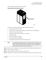
Switch on each SPU cabinet shipped with the system.
Figure 4-3SPU Cabinet Power Switch
After you turn on the SPU cabinet power switch, the following events occur:
•
48 V power flows to the SPU cabinet.
•
The 48 V LED on the front and back panels (where the rocker switch is located) goes on.
•
The green LED on each blower turns on.
•
Processor Dependent Code (PDC) starts to run on each cell.
•
Cell selftest executes.
•
Hardware initializes for the cabinet.
•
Console communication is established.
•
The red attention light (on the front and back panel) turns off.
NOTE
If you selected the GSP’s VFP option (on the Main Menu of the GSP screen), you
should see activity at this time. However, if you didn’t select VFP, the Boot Console
Handler (BCH) prompt (Main Menu: Enter command or menu>) should appear
shortly (in about 2 minutes for a two cell partition). If it does not appear, see “If the
Partition Doesn’t Boot to the BCH Prompt” on page 112.
Step 2. When activity on the Reflection 1 screen stops, return to the GSP Main Menu by typing
Ctrl-B
.
Step 3. Enter
co
to enter console mode.
Step 4. Enter the partition number of the partition you want to boot.
Step 5. Press
Enter
once or twice until you see the BCH prompt (Main Menu: Enter command or menu>).
60IN029A
8/9/00
Rocker Switch
48V On/Off
Summary of Contents for 9000 Superdome
Page 8: ...Contents 8 ...
Page 9: ...9 Preface ...
Page 21: ...21 IEC 60417 IEC 335 1 ISO 3864 IEC 617 2 International Symbols ...
Page 22: ...22 Figure 9 Superdome Declaration of Conformity Page 1 ...
Page 23: ...23 Figure 10 Superdome Declaration of Conformity Page 2 ...
Page 24: ...24 ...
Page 32: ...Chapter 1 Introduction Installation Warranty 8 ...
Page 130: ...Chapter 4 Verifying and Booting Superdome Enabling iCOD 106 ...
Page 172: ...Appendix A hp Server rx2600 Support Management Station Configuring the SMS 148 ...
Page 184: ...Appendix C Superdome LAN Interconnect Diagram 160 ...
Page 193: ...Appendix F 169 F A180 Support Management Station ...
Page 230: ...Appendix G Connecting Multiple SPU Cabinets Connecting Cables 206 ...
Page 256: ...Appendix H JUST Exploration Tool Error Conditions 232 ...

