Appendix G
Connecting Multiple SPU Cabinets
Connecting Cables
200
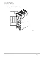
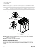
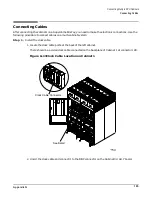
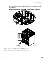
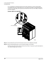
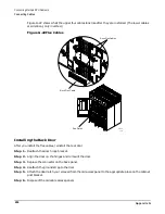
U-turn assemblies are designed to protect the flex cable connectors on single cabinet systems.
These assemblies must be removed before you can install the flex cables on a Superdome 64 Way.
There is a U-turn assembly at the top and one at the bottom of the row of flex cable connectors on
each SPU backplane.
Figure G-18U-Turn Assemblies
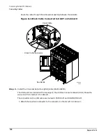
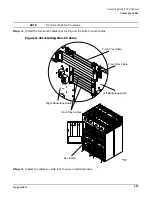
Step 5. Remove the dust covers from the flex cable connectors on the backplane, if present.
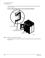
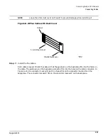
Step 6. Remove the black plastic dust covers from each flex cable as you install it.
Each flex cable comes with two dust covers (only one is shown in Figure G-19), which eliminate the
risk of socket damage due to handling.
60IN073A
10/9/00
U-Turn Assembly
L3-L1
L2-L3
L1-L2
L1-L2
L3-L1
L2-L3
L1-L2
L2-L3
L3-L1
L2-L3
L3-L1
L1-L2
Summary of Contents for 9000 Superdome
Page 8: ...Contents 8 ...
Page 9: ...9 Preface ...
Page 21: ...21 IEC 60417 IEC 335 1 ISO 3864 IEC 617 2 International Symbols ...
Page 22: ...22 Figure 9 Superdome Declaration of Conformity Page 1 ...
Page 23: ...23 Figure 10 Superdome Declaration of Conformity Page 2 ...
Page 24: ...24 ...
Page 32: ...Chapter 1 Introduction Installation Warranty 8 ...
Page 130: ...Chapter 4 Verifying and Booting Superdome Enabling iCOD 106 ...
Page 172: ...Appendix A hp Server rx2600 Support Management Station Configuring the SMS 148 ...
Page 184: ...Appendix C Superdome LAN Interconnect Diagram 160 ...
Page 193: ...Appendix F 169 F A180 Support Management Station ...
Page 230: ...Appendix G Connecting Multiple SPU Cabinets Connecting Cables 206 ...
Page 256: ...Appendix H JUST Exploration Tool Error Conditions 232 ...

