Appendix G
Connecting Multiple SPU Cabinets
Preparing Cabinet 0 for Connection
188
Preparing Cabinet 0 for Connection
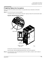
Before you connect the cabinets, prepare Cabinet 0, the left cabinet (as you face the front of the two cabinets):
Step 1. Ensure that the UGUY is set as Cabinet 0.
The cabinet number is clearly marked on the UGUY board, just below the Cabinet Number Switch.
If the switch is not set to 0, you can change it by turning the thumbscrew.
Step 2. Remove the back door of Cabinet 0.
1. Remove the connector to the back panel.
NOTE
Remove the connector from the ribbon cable. Do not remove the ribbon cable from
the back control panel.
2. Remove the grounding strap from the door.
3. Remove the door by lifting it up and off of its hinges.
4. Remove the hinge bracket.
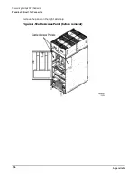
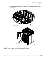
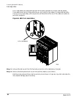
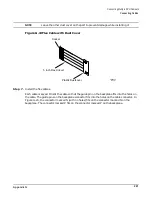
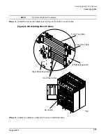
Step 3. Using a T20 driver, remove the cable access panel on the left side as you face the rear of Cabinet 0.
Keep the hardware.
Remove the left panel only. This panel is no longer needed and should be disposed of.
Summary of Contents for 9000 Superdome
Page 8: ...Contents 8 ...
Page 9: ...9 Preface ...
Page 21: ...21 IEC 60417 IEC 335 1 ISO 3864 IEC 617 2 International Symbols ...
Page 22: ...22 Figure 9 Superdome Declaration of Conformity Page 1 ...
Page 23: ...23 Figure 10 Superdome Declaration of Conformity Page 2 ...
Page 24: ...24 ...
Page 32: ...Chapter 1 Introduction Installation Warranty 8 ...
Page 130: ...Chapter 4 Verifying and Booting Superdome Enabling iCOD 106 ...
Page 172: ...Appendix A hp Server rx2600 Support Management Station Configuring the SMS 148 ...
Page 184: ...Appendix C Superdome LAN Interconnect Diagram 160 ...
Page 193: ...Appendix F 169 F A180 Support Management Station ...
Page 230: ...Appendix G Connecting Multiple SPU Cabinets Connecting Cables 206 ...
Page 256: ...Appendix H JUST Exploration Tool Error Conditions 232 ...

