


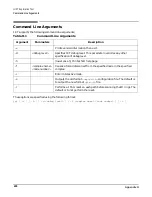


Appendix G
Connecting Multiple SPU Cabinets
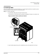
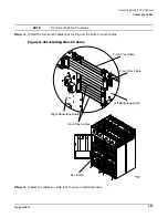
Connecting Cables
204
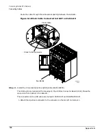
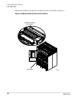
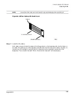
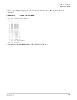
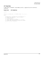
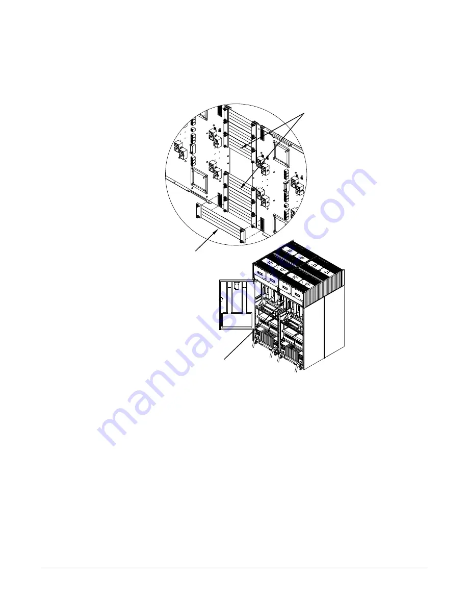
Figure G-22 shows what the upper four cables look like after they are installed. (The lower cables
are identical, only inverted.)
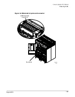
Figure G-22Flex Cables
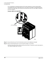
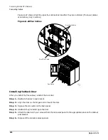
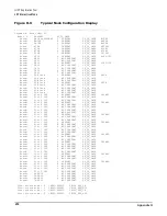
Installing the Back Door
After you install the flex cables, reinstall the rear door.
Step 1. Reattach the door hinge bracket.
Step 2. Align the door on the hinges and remount the door.
Step 3. Replace the connector on the back panel.
Step 4. Reattach the ground strap to the door.
Step 5. Attach the door latch you removed from the old access panel to the appropriate place on the cabinet
post bracket.
Step 6. Dispose of the old cable access panels
60IN071A
1/25/01
See Detail
5 inch Flex Cables
8 inch Flex Cable
L3-L1
L2-L3
L1-L2
L1-L2
L3-L1
L2-L3
L1-L2
L2-L3
L3-L1
L2-L3
L3-L1
L1-L2
Summary of Contents for 9000 Superdome
Page 8: ...Contents 8 ...
Page 9: ...9 Preface ...
Page 21: ...21 IEC 60417 IEC 335 1 ISO 3864 IEC 617 2 International Symbols ...
Page 22: ...22 Figure 9 Superdome Declaration of Conformity Page 1 ...
Page 23: ...23 Figure 10 Superdome Declaration of Conformity Page 2 ...
Page 24: ...24 ...
Page 32: ...Chapter 1 Introduction Installation Warranty 8 ...
Page 130: ...Chapter 4 Verifying and Booting Superdome Enabling iCOD 106 ...
Page 172: ...Appendix A hp Server rx2600 Support Management Station Configuring the SMS 148 ...
Page 184: ...Appendix C Superdome LAN Interconnect Diagram 160 ...
Page 193: ...Appendix F 169 F A180 Support Management Station ...
Page 230: ...Appendix G Connecting Multiple SPU Cabinets Connecting Cables 206 ...
Page 256: ...Appendix H JUST Exploration Tool Error Conditions 232 ...