


Chapter 3
Preparing Superdome for Booting
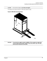
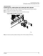
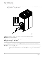
Attaching Side Skins and Blower Side Bezels
37
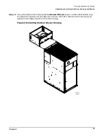
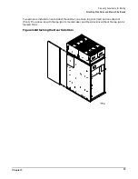
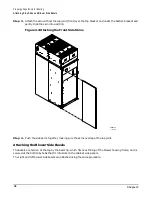
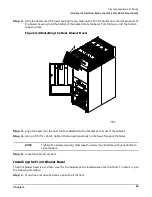
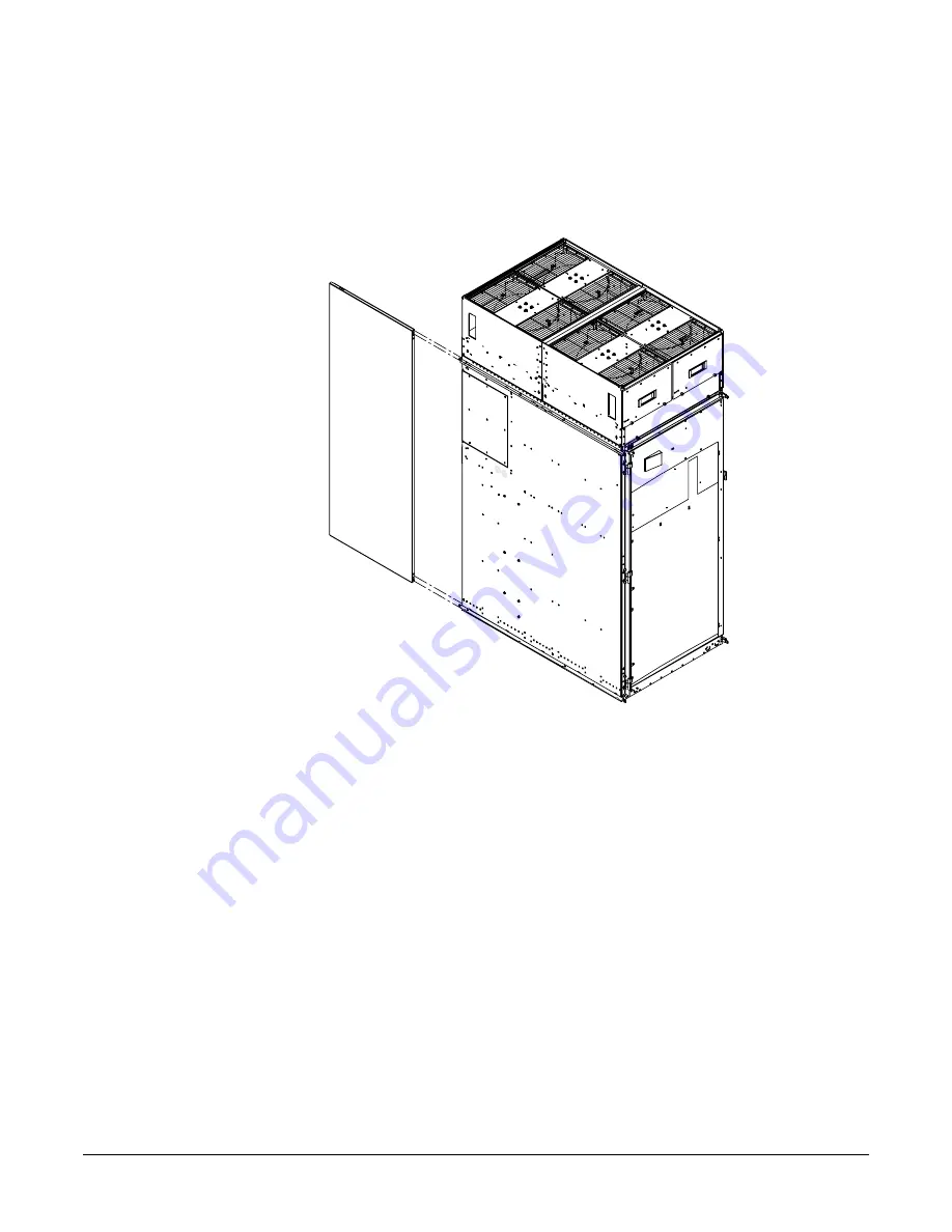
Two skins are installed on each side of the cabinet, one has a lap joint (rear) and one does not
(front). The side skins with the lap joint is marked Rear and the side skins without the lap joint is
marked Front.
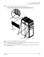
Figure 3-6Attaching the Rear Side Skin
7/24/00
60IN045A
Summary of Contents for 9000 Superdome
Page 8: ...Contents 8 ...
Page 9: ...9 Preface ...
Page 21: ...21 IEC 60417 IEC 335 1 ISO 3864 IEC 617 2 International Symbols ...
Page 22: ...22 Figure 9 Superdome Declaration of Conformity Page 1 ...
Page 23: ...23 Figure 10 Superdome Declaration of Conformity Page 2 ...
Page 24: ...24 ...
Page 32: ...Chapter 1 Introduction Installation Warranty 8 ...
Page 130: ...Chapter 4 Verifying and Booting Superdome Enabling iCOD 106 ...
Page 172: ...Appendix A hp Server rx2600 Support Management Station Configuring the SMS 148 ...
Page 184: ...Appendix C Superdome LAN Interconnect Diagram 160 ...
Page 193: ...Appendix F 169 F A180 Support Management Station ...
Page 230: ...Appendix G Connecting Multiple SPU Cabinets Connecting Cables 206 ...
Page 256: ...Appendix H JUST Exploration Tool Error Conditions 232 ...