3-10
Normalization
Adjusting the Power Monitor
Adjusting the Power Monitor
Perform this procedure when the system is first installed; it does not need to
be performed before each individual measurement. In the following proce-
dure, you’ll need an optical power meter.
1
On the
System
menu, confirm that the
Wavelength Meter
command is checked.
The check mark can be toggled on and off by clicking the command.
2
Connect a short "through" fiber-optic cable between the front-panel
SOURCE
OUTPUT
to
RECEIVER INPUT
connectors.
3
Click the
Modulator Bias
button.
The modulator is automatically biased to the optimum (quadrature) perfor-
mance condition. Bias adjustment is performed at the beginning of a measure-
ment session. It does not need to be performed before each individual
measurement. Bias adjustment can be set to occur automatically when a nor-
malization is performed.
4
On the
Service
menu, click
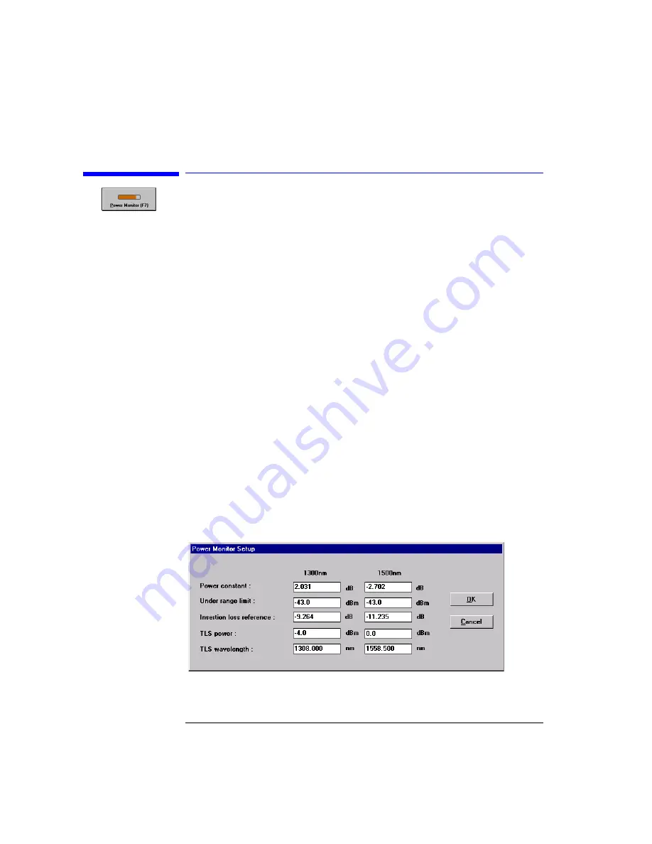
Power Monitor Settings.
For dual band systems, enter high band values in the following steps. If you
have a single band system, perform these steps to enter the values for the sin-
gle available band.
Figure 3-2. Power Monitor Setup Window
Summary of Contents for 86037B
Page 1: ...User s Guide HP 86037B Chromatic Dispersion Test System ...
Page 31: ...2 13 Operation The Main Window Figure 2 4 Repeat Measurement Selector ...
Page 72: ...3 16 Normalization Setting Normalization Preferences ...
Page 94: ...4 22 Remote Control TES Parameters Main chromatic dispersion screen ...
Page 100: ...4 28 Remote Control TES Parameters CD and Gain Measurement Settings Dialog Box ...
Page 102: ...4 30 Remote Control TES Parameters Length Measurement Settings Dialog Box ...
Page 104: ...4 32 Remote Control TES Parameters Normalization Settings Dialog Box ...
Page 106: ...4 34 Remote Control TES Parameters New Normalization Button Dialog Box ...
Page 120: ...4 48 Remote Control Output Parameters ...
Page 158: ...5 38 Maintenance Hewlett Packard Sales and Service Offices ...
Page 170: ...6 12 Installation Installation ...
Page 174: ...7 4 Reference Theory of Operation Figure 7 3 HP 86037B Block Diagram Options 121 and 122 ...
Page 175: ...7 5 Reference Theory of Operation Figure 7 4 The HP 86037B Option 114 block diagram ...
Page 190: ...7 20 Reference System Options ...
Page 191: ...8 Specifications 8 3 Regulatory Information 8 7 Specifications and Regulatory Information ...
Page 204: ...Index 6 Index ...


