


8 Channel 2.4 GHz Aircraft Computer Radio System
8 Channel 2.4 GHz Aircraft Computer Radio System
Section 1: Introduction
Section 1: Introduction
14
15
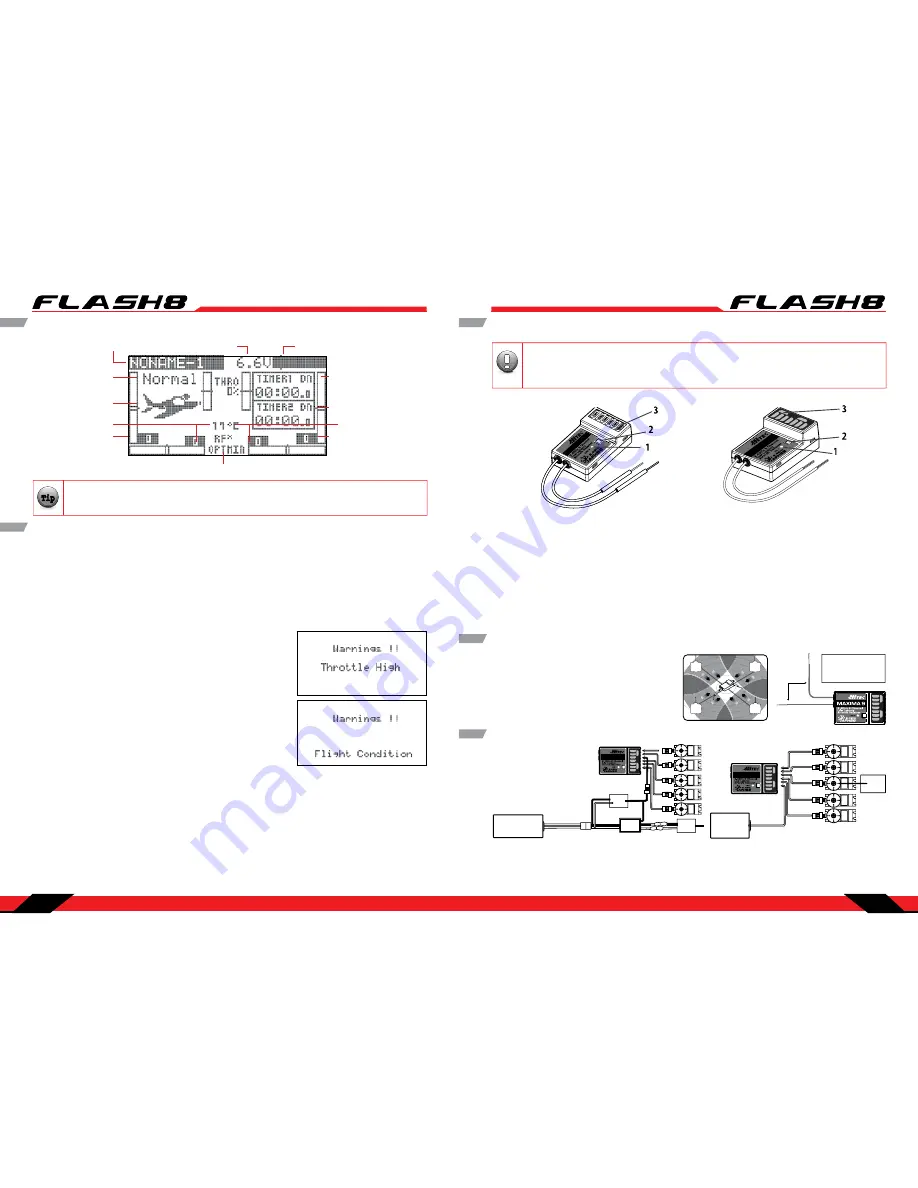
Main Menu
Model Name
Battery Voltage
Battery Capacity Remaining
Model Type
Flight Condition
Spectra Reciever Type Setting
Timer number and Type
RX Voltage(SPC)
Total in Use Time for
Model Memory Slot
Left Trim Indicators
Right Trim Indicators
Transmitter Warnings
The Flash 8 has a few warning alarms that you should be aware of.
Start Up Warnings
If the transmitter continuously beeps and the logo light flashes red and blue immediately after turning on
the power, read the warning message displayed on the screen. The Flash 8 will not transmit a radio signal
until all start-up warnings have been corrected. If UI Feedback is turned off, the transmitter will not beep
during active warnings. The logo light will flash red and blue regardless of the UI Feedback setting. (See
Section Three: System Menu Programming for instructions on configuring UI Feedback.)
- High Throttle
If the throttle is positioned above idle during the system “boot-
up to transmit” process, a warning beep will occur and the
following warning screen will be displayed.
- Condition on Warning
If you have flight conditions and other mixing programmed for
the active model and they are switched “on” during the “boot-
up to transmit” process, a warning sound will occur and the
following warning screen will be displayed.
From the main menu, you can quickly access certain settings by scrolling to them and pressing
the jog dial.
Note
Tip
Tip
Tip
Caution
Throttle Lock
In Flight Warnings
If the transmitter should start a continuous beeping during flight, land immediately and evaluate the
cause of the warning. There are two warnings that may occur in flight.
- Low Transmitter Battery Warning
When the transmitter battery power falls to a critically low level, a warning sound will occur.
- Low Aircraft Battery Warning
When using the Optima series of receivers and the on-board battery or the battery connected to the SPC
port is critically low, your transmitter will start beeping warning you that you should land immediately.
This feature does not occur when using single direction receivers such as the Maxima and Minima series
of receivers.
1. Function Button:
Used for binding the receiver to the Flash 8 and entering the FAIL-SAFE or Hold
feature.
2. Dual LED Status Indicator:
Indicates the set-up process codes and current status of the receiver.
3. Channel Output and Battery Input Ports:
The ports for battery power input and servos, gyros and
other accessories’ output ports are located at the side end of the Maxima receivers.
4. Low Battery Warning:
If the receiver’s battery levels fall below 3.6V, the RED LED will flash.
5. FAIL-SAFE/Hold Mode Selectable:
Servos and other accessories position can be set with a FAIL-SAFE
point if power to the receiver is lost.
Maxima Series Receivers
MA XIMA
6
MA XIMA
9
CH1 CH2
CH3 CH4
CH5 CH6
CH7
CH8
BAT/
9
MAXIMA 6
MAXIMA 9
Maxima Series Receiver Antenna Installation
The Maxima receiver series antenna system was
created to provide the optimum signal capture
capability. Our two antennas must be installed
properly. Refer to the illustration below.
TX
TX
TX
TX
RX
90
˚
Recommended installation
method to optimize
receiver performance
CH1
CH2
CH3
CH4
CH5
CH6
CH7
CH8
BA
T/9
Electric powered aircraft with Electronic Speed Control
Use this method on electric planes using ESCs
providing power to the receiver and servo functions.
Maxima Series Receiver Connection Diagrams
CH1
CH2
CH3
CH4
CH5
CH6
CH7
CH8
BA
T/
9
SE
RV
O
SE
RV
OS
ER
VO
SE
RV
O
Power Battery
Motor
SE
RV
O
BEC
ESC
Glow, gas or electric powered aircraft using a
separate receiver battery supply.
Follow this connection diagram when using a
regulated Li-Po, or 4.8 to 6V receiver battery.
CH1
CH2
CH3
CH4
CH5
CH6
CH7
CH8
BA
T/9
SER
VO
SER
VO
SE
RV
O
SER
VO
Receiver
Battery
SE
RV
O
Engine
The Maxima series is designed for use with G2 AFHSS radios such as the Aurora 9X and Flash
series. USE ONLY Digital SERVOS with the Maxima receivers. Analog servos cannot be used with
the Maxima series receivers.
Warning
Note
Tip
Tip
Tip
Caution


