background image

8 Channel 2.4 GHz Aircraft Computer Radio System

8 Channel 2.4 GHz Aircraft Computer Radio System

Section 6: Heli Programming Menu

Section 6: Heli Programming Menu

100

101

Swash to Throttle Mixing cont.

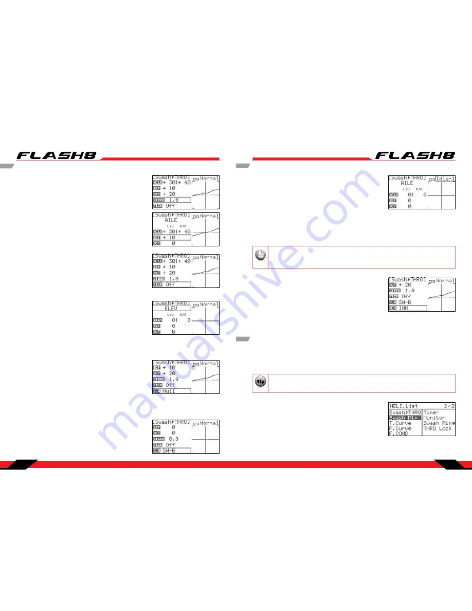
11. Scroll to highlight the “OST” (Offset) field and press the jog 
dial to activate the menu. 

12. Rotate the jog dial to select the desired amount of offset and 
press the jog dial to enter your selection. 

13. Scroll to highlight the “SPEED” field and press the jog dial to 
activate the menu. 

14. Scroll to define the amount of time (0.0 to 10.0 seconds) to 
transition the settings when this mix is enabled. Press the jog 
dial to confirm your selection. 

15. Scroll to highlight the “TRIM” field and press the jog dial to 
activate the menu. 

16. Rotate the jog dial to select “ON” or “OFF” and press the jog 
dial to confirm your selection. When “ON” is selected, the mix 
reacts to trim adjustments of the ailerons. Otherwise, the mix 
ignores aileron trim changes. 
17. If you wish to adjust the mix for elevator inputs, scroll back 
up to the function field and press the jog dial to activate the 
menu. Otherwise, skip to step 20.

18. Rotate the jog dial to select “ELEV” and press the jog dial to confirm your selection. 

19. Repeat steps 6-16 to input throttle compensation values for elevator inputs.

20. Scroll to highlight “S/W” and press the jog dial to activate the 
switch menu. 

21. Scroll to select a switch to activate the swash-throttle mix. Press the jog dial to confirm your selection.

a. If you choose the “NULL” option, the set mix values will remain active at all times for this model. 

b. If you choose a switch:
- The current switch position will be displayed in the top right 
field of the display as “0”, “1”, or “2”. 
- Repeat steps 4-19 as applicable to define a swash-throttle mix 
for every switch position.

Swash to Throttle Mixing cont.

If you are using multiple flight conditions, you must define swash-throttle mix values for each 
flight condition. The top field of the Swash>Thro menu allows you to select the desired flight 
condition. Alternately, you may select the desired flight condition using the assigned F.Cond switch.

Warning

Note

Tip

Tip

Tip

Caution

To disable the swash-throttle mix: 

1. Scroll to highlight the “MIX” field in the Swash>Thro menu and 
press the jog dial to activate the menu. 

2. Select “INH” (inhibit) and press the jog dial to confirm your 
selection. 

3.  Press the Back button to return to the Model Function menu.

Swash Mix

Swash Plate Adjustment Menu:

Use the swash mix feature to apply a fine adjustment to the swash plate travel. For the very best accuracy, 
we recommend the use of a swash plate leveling set-up tool.

As this is a set-up feature, swash mix is one of the few functions that is NOT influenced by flight 
conditions, idle-up or hold conditions.

Warning

Note

Tip

Tip

Tip

Caution

Our example will show a 120CCPM head format:

1. From the model menu, scroll to highlight “Swash Mix” and 
press the jog dial once to enter the sub trim menu. 
2. Scroll to the functions (AILE,ELEV,Pitch) to be adjusted and 
press the jog dial to activate the menu.

22. To set up the Swash to Throttle mixing in accordance with a 
Flight Condition:
− The upper right field of the menu displays which flight 
condition is currently active and will be programmed. 
− Scroll to the Flight Condition field and press the jog dial to 
activate the menu.
− Choose the desired flight condition and press the jog dial to 
confirm your selection.

23. Press the Back button to return to the Model Function menu.

Summary of Contents for Flash8

Page 1: ...8 Channel 2 4 GHz Aircraft Computer Radio System...

Page 2: ...ell LiFe Battery This device complies with part 15 of the FCC Rules Operation is subject to the following two conditions 1 This device may not cause harmful interference 2 This device must accept any...

Page 3: ...Working with the Common Model Function Menus 45 Servo Reverse 46 Sub Trims 46 Dual Rates 47 Exponentials 48 Switch Assignment 48 End Point Adjustments 49 Servo Speed 50 Programmable Mixes 51 Timers 5...

Page 4: ...ons to keep you and others safe Are you experienced Flying models is not an intuitive process Most accomplished model pilots were taught by another modeler We encourage you to seek help during your ea...

Page 5: ...inister your repair visit our web site at www hitecrcd com to download the repair form Complete the form and send in your item for repair Hitec Service 12115 Paine St Poway CA 92064 858 748 6948 servi...

Page 6: ...rcuit from an Electronic Speed Control Current Drain 30mA Minima Series 2 4GHz Receivers Model Size Weight Stock Number Minima 6 T 1 19 x 0 81 x 0 27in 30 4 x 20 8 x 7 1mm 0 22oz 6 5g 26610 Minima 6 E...

Page 7: ...e light changes to green the battery is fully charged Transmitter Controls Make sure you use a charger suitable for the battery pack you are using It is recommended that you remove the battery from th...

Page 8: ...d the on board battery or the battery connected to the SPC port is critically low your transmitter will start beeping warning you that you should land immediately This feature does not occur when usin...

Page 9: ...jog dial to FINISH the binding process Make sure all functions are working properly before flying your model OPTI M A 7 6 OPTI M A 9 MINI M A 6E MINI M A 6T 6T output block is on top 6 OPTI M A 6 OPTI...

Page 10: ...connection diagram when using a regulated Li Po or 4 8 to 6V receiver battery BAT CH7 CH6 DATA SPC LED LINK LED LINK CH1 CH2 CH3 CH4 CH5 OPTI M A 7 OPTI MA 7 2 4G Hz 7 Channel Ai r cr af t Re cei ver...

Page 11: ...of safety we recommend that FAIL SAFE should always be activated and the FAIL SAFE settings should be selected so as to bring the model to a non critical situation e g motor idle electric motor OFF co...

Page 12: ...ession you perform a range check that confirms that the signal between the receiver and transmitter is strong To do a range check use a power down mode to reduce the transmitter signal strength During...

Page 13: ...ll to the SLT receiver SLT Binding The following procedure is for binding typical SLT receivers to the Flash 8 These methods may vary from manufacturer to manufacturer Check your receiver manual for a...

Page 14: ...elect NEW to create a new model For safety reasons remove the propeller s from electric aircraft during radio system setup Warning Note Tip Tip Tip Caution If you are setting up a powered or un powere...

Page 15: ...tion menu If your receiver is not bound linked to your transmitter you will need to follow the procedures on page 16 to do so Note Tip Tip Tip 5 Select the first default model NONAME 1 and press the j...

Page 16: ...how long the backlight remains active CONTRAST Adjusts the screen contrast BATTERY Used to specify the battery type used in the transmitter NiMh NiCD LiPo or LiFe UI FEEDBACK Turns the user interface...

Page 17: ...og dial to confirm your entry You can only reset an active model Note Tip Tip Tip Model Select Menu cont Rename a model a In the model select menu highlight the model you wish to rename Press the jog...

Page 18: ...your wing and tail choices Scroll to WING and press the jog dial to activate the menu Model Type ACRO Menu Programming cont Model Type GLID Menu Programming 6 Scroll to TAIL and press the jog dial to...

Page 19: ...he jog dial to confirm your selection 6 Scroll to TAIL and press the jog dial to activate the menu The choices for tail type are dependent on the type of wing you selected 7 Select the tail type for y...

Page 20: ...selection 7 Use the back button to return to the System Menu Trim Step The Trim Step screen is utilized to change the amount of movement seen on the servos with each adjustment or beep of the gimbal...

Page 21: ...he Optima series of telemetry capable receivers the Flash 8 has the ability to communicate a variety of information from the airplane directly to the transmitter Refer to Section Seven Using the Telem...

Page 22: ...8 s hardware adjustments refer to Appendix A Hardware Adjustments Note Tip Tip Tip 1 From the System Menu scroll to highlight MODE and press the jog dial to enter the mode selection menu 2 Press the...

Page 23: ...on as well as options which are specific to fixed wing models ACRO GLID or helicopters HELI This section illustrates the common model function options The features specific to fixed wing or helicopter...

Page 24: ...ming aerobatics One or more switches are assigned to allow the pilot to select high or low rates Exponential Rate EXP is a powerful function that is often used to make a twitchy model easier to contro...

Page 25: ...es for this function and press the jog dial to confirm your selection If you choose one of the 3 position switches you can set triple rates high mid low 17 Physically move the switch to the desired po...

Page 26: ...ling with models that require small control movements or in cases where binding damage could occur from excessive control movement Servo Speed 3 Rotate the jog dial clockwise or counter clockwise to a...

Page 27: ...ivate the menu 8 Rotate the jog dial to highlight the L U left up the R D right down field or both fields If you want the mix affect the movements of the slave servo equally in both directions highlig...

Page 28: ...ction menu 28 To inhibit this mix scroll to the MIX field and press the jog dial to activate the menu 29 Scroll to select INH and press the jog dial to confirm your selection 30 Press the back button...

Page 29: ...firm your selection Scroll to highlight the middle field and press the jog dial to activate the menu Move the throttle stick to the position where you want the timer to turn on We suggest a position j...

Page 30: ...o their neutral position including all trim or sub trim settings This screen is useful to position the servos when setting pushrod lengths for control surfaces 9 The neutral setting can be halted by e...

Page 31: ...s T CURVE ACRO only Specify non linear throttle response If you have not already programmed a model with the preceding quick start guide we encourage you to do so before tackling the model programming...

Page 32: ...active flight condition Note Tip Tip Tip aution Press the backbuttontwicetoreturntotheflightconditionsmenu Flight Conditions cont 7 Press the back button to return to the flight conditions menu and re...

Page 33: ...ay select the desired flight condition using the assigned F Cond switch Note Tip Tip Tip 2 Scroll to the top AILE field and press the jog dial to activate the menu Elevon Mixing cont 3 Scroll to highl...

Page 34: ...a pitch up command is given Press the jog dial to confirm your input 1 From the model menu rotate the jog dial to highlight V Tail Mix and press the jog dial once to enter theV tail mix menu 5 Scroll...

Page 35: ...counter clockwise the desired servo endpoint when a pitch down command is given Press the jog dial to confirm your input 1 From the model menu rotate the jog dial to highlight Ailevator and press the...

Page 36: ...tial travel when yaw commands are given 9 Scroll to highlight the OST Offset field and press the jog dial to activate the menu 10 Rotate the jog dial to set the increase decrease amount of Offset for...

Page 37: ...To configure an elevator to camber mix 1 From the model menu rotate the jog dial to highlight ELEV CAMB and press the jog dial once to enter the activation menu 2 Press the jog dial again to activate...

Page 38: ...ld in the top right corner of the screen will indicate when the mix is active 23 Press the back button to return to the model function menu If you are using multiple flight conditions you must define...

Page 39: ...al to confirm your selection a If you choose the NULL option the mix will remain inactive at all times for this model b If you choose a switch The switch position menu will appear Scroll to highlight...

Page 40: ...to increase clockwise or decrease counter clockwise the desired servo endpoint for the when the flap is fully deployed 9 If the model has a second flap servo repeat steps 4 8 on the FLP2 row of the v...

Page 41: ...servo angle when the mode is activated Press the jog dial to confirm your input 9 If a second elevator set up for the airplane is needed repeat the steps 7 8 to move ELEV2 field 10 Scroll to highlight...

Page 42: ...ivate the menu 2 Select INH inhibit and press the jog dial to confirm your selection 3 Press the back button to return to the model menu Butterfly Mixing B FLY GLID Only cont 7 Scroll to highlight the...

Page 43: ...right corner of the screen will indicate when the mix is active 20 Press the back button four times to return to the model function menu Butterfly Mixing B FLY GLID Only cont If you are using multipl...

Page 44: ...ndition field and press the jog dial to activate the menu Choose the desired flight condition and press the jog dial to confirm your selection 11 Press the back button to return to the model function...

Page 45: ...e the jog dial to input the desired throttle position at this point on the curve Throttle stick full down 6 Scroll to highlight the 2 field and press the jog dial to activate 7 Rotate the jog dial to...

Page 46: ...ramming Menu When the active model is configured as a helicopter model type the model function menu contains programming options which are useful for helicopters This section describes the features an...

Page 47: ...u Rotate the jog dial to select Nor normal or T lock throttle lock Throttle lock is used for bench testing the gyro rate sensitivity Gyro cont 6 Scroll to highlight S W and press the jog dial to activ...

Page 48: ...ion Scroll to select ON and press the jog dial to confirm your selection If you toggle the selected switch the field in the top right corner of the screen will indicate when the mix is active The mome...

Page 49: ...Press the back button to return to the REVO Mix menu 4 Scroll to the 1 field and press the jog button to activate the menu 5 The left field is the tail rotor pitch and the right field is the throttle...

Page 50: ...d and press the jog dial to activate the menu Choose the desired flight condition and press the jog dial to confirm your selection 19 Press the Back button to return to the Model Function menu Swash t...

Page 51: ...ayed in the top right field of the display as 0 1 or 2 Repeat steps 4 19 as applicable to define a swash throttle mix for every switch position Swash to Throttle Mixing cont If you are using multiple...

Page 52: ...te the jog dial to highlight T Curve and press the jog dial once to enter the activation menu 2 Press the jog dial again to activate the menu 3 Rotate the jog dial to select ACT activate then press th...

Page 53: ...t the MIX field in the throttle curve menu and press the jog dial to activate the menu 2 Select INH inhibit and press the jog dial to confirm your selection 3 Press the Back button to return to the mo...

Page 54: ...s you actuate the relevant controls These values are reflected in the graph as well Pitch Curve cont The Flash 8 allows you to program up to five flight conditions This powerful feature lets you defin...

Page 55: ...travel of the servos attached to the helicopter swash plate This can be used to help prevent binding of the control system when using large control movements for aerobatics To configure swash ring 1 F...

Page 56: ...ad batteries an empty fuel tank or overheated components Additionally telemetry data is priceless when fine tuning your model to reach the peak of its performance capability With each tweak to your mo...

Page 57: ...the jog dial to confirm your selection 4 Scroll to the ALT field and press the jog dial to confirm your selection 1 From the sensor menu rotate the jog dial to highlight RPM and press the jog dial on...

Page 58: ...e the jog dial to select the C50 or C200 and press the jog dial to confirm your selection 8 Press the back button to return to the sensor menu Advanced The Advanced screen displays airspeed data colle...

Page 59: ...nts at noisy flying sites and or avoid disturbing nearby pilots Advanced cont Stick Length Adjustment Stick Lever Tension Adjustment Mode Change Hands come in all sizes so to accommodate everyone we u...

Reviews: