Instruction manual
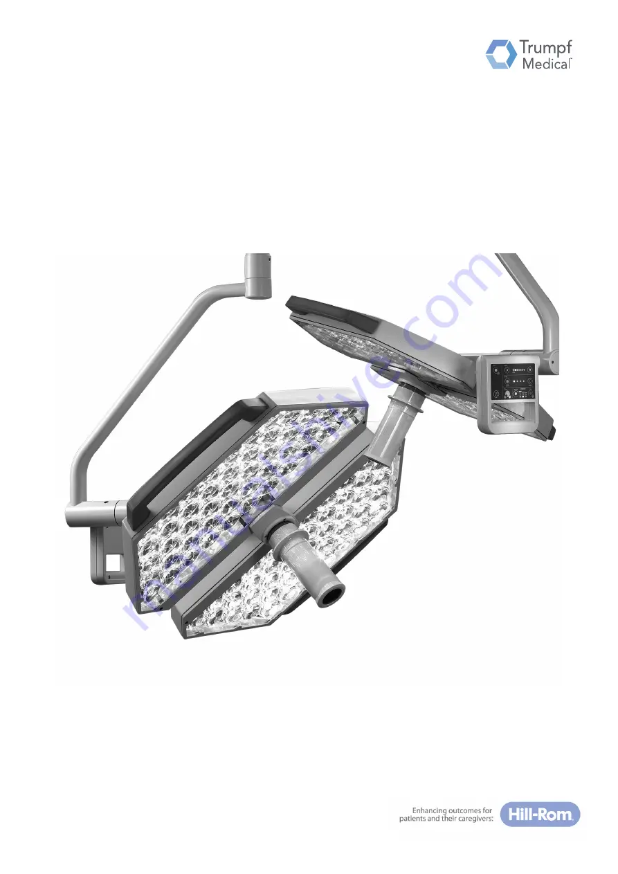
TruLight 5000/3000 lighting system
Read the instruction manual before using the product and store for later reference.
Englischen-GB
Page 1: ...Instruction manual TruLight 5000 3000 lighting system Read the instruction manual before using the product and store for later reference Englisch en GB ...
Page 2: ...55000 00011_002_01 1756789 2017 09 06 2 ...
Page 3: ...ting system including the combination of two to three surgical lights mounted on the ceiling Optional equipment such as light head with camera or laser Light head For both machine versions TruLight 5000 and TruLight 3000 both the large light head Ø 730 mm as well as the small light head Ø 640 mm are available with various adjustments for the size of the field of illumination light intensity and co...
Page 4: ...eiss Straße 7 9 07318 Saalfeld Germany www trumpfmedical com Telephone 49 3671 586 0 Fax 49 3671 586 41165 E mail info trumpfmedical com Technical Customer Service TRUMPF Medizin Systeme GmbH Co KG Carl Zeiss Straße 7 9 07318 Saalfeld Germany Telephone 49 3671 586 41911 Fax 49 3671 586 41175 Email Service wwo trumpfmedical com ...
Page 5: ... by any person or company Modifications and translations Modifications to the device We constantly work on the further development of our products and reserve the right to make changes to the scope of delivery in terms of form equipment and technology Changes to the instruction manual The content of the instruction manual can be changed at any time without prior notice Please keep up to date on th...
Page 6: ...nationally applied standards 13 1 8 4 Intended use 13 1 8 5 Special features 14 1 8 6 Improper use 14 1 9 Ambient conditions for operation and storage 14 1 9 1 Ambient conditions for operation 14 1 9 2 Ambient conditions for storage 14 1 10 Combination with other medical devices 15 1 11 Disposal 15 2 Safety instructions 16 2 1 Structure of the safety instructions in this instruction manual 16 2 1 ...
Page 7: ...ositioning the light head 32 5 4 2 Operating the light heads 32 5 4 3 Controlling the light intensity 34 5 4 4 Sterile Light Control SLC function optional 35 5 4 5 Adaptive Light Control ALC function optional 36 5 4 6 Adaptive Light Control plus ALC plus function optional 37 5 4 7 Controlling the light field 38 5 4 8 Controlling the colour temperature optional 39 5 4 9 Synchronisation of the colou...
Page 8: ...66 11 3 Maintenance every two years 67 11 4 Repairs 67 12 Adjustments 68 12 1 Setting spring arm swivel range type AC2000 LCH 68 12 1 1 Disconnecting the power to the lighting system 68 12 1 2 Setting the swivel range 68 12 2 Setting spring arm swivel range type AC 2000 and type AC 3000 69 12 2 1 Disconnecting the power to the lighting system 69 12 2 2 Setting the swivel range 69 12 3 Setting spri...
Page 9: ...e cardan joint rod 76 12 7 6 Setting the braking force of the cardan joint axle on the standard light head 77 12 7 7 Setting the braking force on the light head SLC ALC plus 78 12 7 8 Setting the cardan joint axis braking force on the standard light head with camera 79 13 Consumables 80 14 Troubleshooting 81 15 Technical data 82 15 1 Equipment versions for the light models 82 15 2 Device data 82 1...
Page 10: ...who owns a device and is authorised to use it or by whose authority the device is used The operator is obliged to provide a safe device and appropriately instruct the user regarding operation and proper use of the device 1 3 2 User Users are individuals who by their qualifications or an appropriate briefing by specialist personnel are authorised to operate and work with the device Users are fully ...
Page 11: ...ntended and is operated and maintained in accordance with the provisions of this instruction manual only original spare parts or accessories approved by Trumpf Medical are used no modifications are made to the device inspections and maintenance work are carried out at the time intervals specified an initial commissioning is carried out and the device is released for operation with a handover decla...
Page 12: ...Saalfeld Germany 1 7 Information for users Note that the device may only be operated by persons who have had the corresponding instruction 1 7 1 Training for use of the device Instruction Training must be carried out directly at the device by qualified staff of the operator or by an installer of the device who has been authorised by the manufacturer At the end of the briefing it must be documented...
Page 13: ...01 1 2 IEC 60601 1 2 Medical electrical equipment Electromagnetic compatibility 1 8 3 Internationally applied standards UL 60601 1 ANSI AMI ES 60601 1 CAN CSA C22 2 No 60601 1 IEC 60601 1 IEC 60601 1 2 1 8 4 Intended use Intended use The device is intended for use in a patient environment in hospitals or medical practices to illuminate a part of the patient with high light intensity for examinatio...
Page 14: ...C plus function to measure distance is classified as a class 2 laser and has the following specifications max output power 0 95 mW wave length 620 690 nm beam divergence 0 16 x 0 6 mRad pulse duration 0 4 x 10 9 s pulse refresh rate 320 MHz 1 8 6 Improper use Improper use Additional load on the light support is not permitted The device may not be exposed to severe vibration Restriction The device ...
Page 15: ...iance with this standard must be ensured by the service technician responsible No BF or CF Class application components according to IEC 60601 1 may be directly connected Devices of third party manufacturers in the patient environment must have safety levels equivalent to that of the TruLight 5000 3000 lighting systems Devices of third party manufacturers outside the patient environment must have ...
Page 16: ...TTENTION indicates a potentially dangerous situation in which non compliance may cause damage to property 2 1 3 Indicating additional information NOTE provides you with additional information and helpful tips for safe and efficient use of the device 2 2 Additional symbols for the safety information Gas explosion warns against the explosive ignition of gas mixtures Electric shock warns against an e...
Page 17: ...for a range of reasons Installation dismantling of the securing ring Only to be performed by authorised service personnel The detailed instructions relating to the installation dismantling of a securing ring must be complied with Sensor marking identifies the class of the laser product installed for distance measurement according to IEC 60825 1 Edition 2 0 2007 03 and IEC 60825 1 Edition 3 2014 2 ...
Page 18: ...rts of the surgical light and the patient at the same time Surgical interventions in the field of vision Damage to vision In case of surgery in the field of vision of the patient the high light intensity by the light heads may cause eye fatigue or damage to vision The eyes of the patients must be closed covered or protected e g with protective goggles Do not look directly into the light emitting s...
Page 19: ...ad does not achieve the specified light intensity Take the lighting system out of service Inform Trumpf Medical Customer Service Exchanging a light head or repairs to the lighting system may only be performed by Trumpf Medial Customer Service or by service staff trained and authorised by Trumpf Medical Additional loads Crashing of the light system Do not place any additional weight on the light sy...
Page 20: ...rer for use with the following materials Polycarbonate PC polyamide PA acrylonitrile butadiene styrene copolymer ABS polystyrene PS polyurethane PUR polyphenylene sulphone PPSU polybutylene terephthalate PBT and silicones In the event of an increased layer formation of surface disinfectant thorough cleaning must be performed Due to the risk of surface damage Do not use sharp pointed or abrasive ob...
Page 21: ... position the spring arm will shoot up and can cause severe injuries The light head flat screen may therefore only be de installed by Trumpf Medical Customer Service Commissioning Initial commissioning prior to use The light system must be handed to the user in a tested state after initial operation before it can be used in routine medical procedures The initial operation includes functional and s...
Page 22: ...for a working distance of approximately 0 8 metres 1 0 meter and 1 2 meters are selected on the control panel or the optional wall mounted control panel The light head then automatically selects the optimum light setting for this working distance Adaptive Light Control plus ALC plus optional Adaptive Light Control plus ALC plus enables the targeted electronic control of various LEDs in order to ac...
Page 23: ...tting UV ultraviolet radiation High failure safety The use of a large number of LEDs makes the light head very resistant to failure Failure of single LEDs does not affect the function of the light head 3 3 Accessories Dock Desk Material no 1839155 Dock Desk WallControl Panel Material no 1992641 TCO Wall Control Universal Front Interf Material no 1956143 Wall Control Preinstall Set FLUSH Material n...
Page 24: ...s permitting the supply of the correct spare parts The serial numbers iden fy the individual components of a device 4 1 1 Position of the serial numbers on the ceiling mounted version A Ceiling mounted version The name plate with the main serial number is on the topmost beam Serial numbers of the individual components are provided at Ceiling conduit Interface plate Boom Spring arm Quarter bracket ...
Page 25: ...ile stand version The ra ng plate with the main serial number is on one side of the power adapter housing Serial numbers of the individual components are provided at Boom Light head Stand base 4 1 4 Position of the laser marking D Light head with Adaptive Light Control plus ALC plus The laser marking is provided in the suspension area of the light head housing ...
Page 26: ...ds on AC 2000 or AC 2000 LCH Low Ceiling Height spring arms 5 1 2 Components of the ceiling mounted version The lighting system comprises of Ceiling cover panel Ceiling conduit Boom AC 2000 or AC 2000 LCH Low Ceiling Height spring arm Convenience bracket Light head 5 1 3 Camera on light head optional The light heads can be equipped with an op onal camera see the Instruc on Manual TruVidia SD or Tr...
Page 27: ...ge A boom at the ceiling conduit Full horizontal rotation movement 360 Hinge B AC 2000 type spring arm on the boom Horizontal rotation movement 360 Vertical swivel movement in the range 45 to 50 Hinge C convenience bracket at the spring arm type AC 2000 Full horizontal rotation movement 360 Hinge D light head on the convenience bracket TruLight 3000 Full vertical rotation movement 360 TruLight 500...
Page 28: ...urgical light as single light with a small light head on the AC 2000 type spring arm 5 2 2 Components of the wall mounted version The lighting system comprises of Wall support Boom AC 2000 or AC 2000 LCH Low Ceiling Height spring arm Convenience bracket Light head 5 2 3 Size of the light heads For both light head versions TruLight 5000 and TruLight 3000 both the large light head Ø 730 mm as well a...
Page 29: ...ints of the support arms when there is sufficient distance from neighbouring walls and objects AC 2000 type spring arm Hinge A boom at the wall support Horizontal rotation movement 200 Hinge B AC 2000 type spring arm on the boom Full horizontal rotation movement 360 Vertical swivel movement in the range 45 to 50 Hinge C convenience bracket at the spring arm type AC 2000 Full horizontal rotation mo...
Page 30: ...ly of the mobile stand version The power supply of the mobile stand version is provided at the power supply housing by the mains cable with the IEC power connector for connec on to the IEC power socket on the underside of the power supply housing and with the earthed plug connector for connection to a mains socket Power unit ON OFF switch on the underside of the power supply housing for switching ...
Page 31: ... light head within the ac vity range of the stand The cardan joint facilitates accurate alignment of the light head onto the wound area The following rotation and swivel movements can be performed at the joints of the support arms when there is sufficient distance from neighbouring walls and objects Hinge A spring arm on stand rod Horizontal swivel movement in the range 10 to 10 Vertical swivel mo...
Page 32: ...er handles The operating mode options for the outer handles are described in Chapter 3 1 page 22 5 4 2 Operating the light heads Sterile operation at the handle The light intensity of the TruLight 5000 light version can be adjusted with the sterile handle using the optional Sterile Light Control SLC func on Non sterile operation at the control panels The lighting function of light types TruLight 3...
Page 33: ... panel has the same range of functions as the corresponding control panel on the light head Light intensity Adaptive Light Control ALC TruLight 5000 wall mounted control panel The wall mounted control panel has the same range of functions as the corresponding control panel on the light head Light intensity Colour temperature Colour temperature synchronisation Size of light field Adaptive Light Con...
Page 34: ...ages 10 Endo 40 100 Reducing the light intensity Press key on the control panel The LED for the currently set light intensity lights up Increasing the light intensity Press key on the control panel The LED for the currently set light intensity lights up Endo dimming The light intensity level Endo dimming is intended as the light intensity for endoscopic operations Activating Endo dimming Press key...
Page 35: ...Light 5000 lamp can be adjusted with complete sterility Adjusting the light intensity with Sterile Light Control A touch sensor is installed in the area below the collar of the sterile handle This can be used to adjust the light intensity by a simple finger movement Increasing the light intensity Swipe the finger from left to right Reducing the light intensity Swipe the finger from right to left Th...
Page 36: ...mate working distance of 0 8 m 1 0 m and 1 2 m are selected A for TruLight 3000 on the control panel on the light head or the optional wall mounted control panel or B for TruLight 5000 on the control panel of the control unit or on the optional wall mounted control panel Adjusting the light intensity with Adaptive Light Control TruLight 3000 Select the relevant key on the control panel The light h...
Page 37: ...ad is repositioned during surgery a movement sensor activates the distance detection The distance of the light head from the wound area is automatically detected with the aid of a laser beam The light intensity is automatically adapted to the working distance on the basis of the measurement data Switchover between automatic distance detection and manual adjustment of the distance is performed by p...
Page 38: ...distance of the light head from the wound area Broad light field Ø 23 cm at 1 m distance for a greater distance of the light head from the wound area Adjustment of the size of the light field is performed on the non sterile control panel of the light head or on the relevant op onal wall mounted control panel Activating the narrow field Press the key in the Size section un l the LED lights up Activ...
Page 39: ... Reducing the colour temperature Press key in the Color section until the LED for the required colour temperature lights up Mode of action of the colour temperature The variable colour temperature function is used to increase the colour contrast in the wound area The visual contrast behaviour of the colour temperature is as follows For a wound area which is mainly blue in colour a lower colour tem...
Page 40: ...of the colour temperature of the individual light heads The synchronisation is set in the non sterile area on the control panels on the light head or on the corresponding optional wall mounted control panel For activation the colour temperature value of the light head on which synchronisation is initiated is definitive Synchronising the colour temperature Press key in the Sync section the LED ligh...
Page 41: ...ith damaged electrical components of the mobile stand version Do not connect the stand to the mains in the event of defec ve plug connectors or or damaged mains cables The lighting system is no longer safe to use when the damage described above or other damage occurs Disconnect the lighting system by using the master switch installed in the building or remove the safety connector Ensure that the m...
Page 42: ... sterilisable handle or the non sterile outer handles to posi on the light head 6 2 1 Risks of collision during positioning The lighting system has an impact proof surface coating Collisions may nevertheless damage the lighting system Damage to the light head The area of rotation of the lighting system may be restricted by other components or adjacent walls A collision of the support arm or the li...
Page 43: ... light as single light with a light head on the AC 2000 type spring arm The best possible mobility of the support arms is a V type arrangement Ceiling mounted lighting system B Surgical lighting system as a combination of several light heads on AC 2000 or AC 2000 LCH Low Ceiling Height type spring arms The best possible mobility of the support arms is an M type arrangement ...
Page 44: ...distance measurement must make its measurement within the wound area The sterile handle of the light head must therefore be adjusted so that the laser beam falls inside the wound area Damage to vision Direct contact with the laser beam may cause damage to vision Do not look directly into the laser beam Protect the patient s eyes The patient s eyes must be closed or protected as necessary e g with ...
Page 45: ... the stand The pedestal might lt when the castors are locked and excessive force is exerted onto the spring arm or light head Avoid strong leverage onto the spring arm or the light head Do not add additional loads to the spring arm Locking the stand base The two front castors can be locked to immobilise the stand base Press the brakes of both front castors downwards to lock them Press the brakes o...
Page 46: ...hing reduces the danger of electric shock The mobile stand version Protection Class I may only be connected to a properly earthed safety socket Connect the power supply to the mains 1 Check whether the mains voltage corresponds to the information on the name plate Ask the local energy supply company or a specialist electrical company in cases of doubt 2 Lay the mains cable so that there is no dang...
Page 47: ... off the mobile stand version Switching the mobile stand version to a current free state Switch off the power supply unit position the switch in position 0 see Chapter 6 3 1 page 46 pull the mains cable out of the safety socket The mobile lighting system is disconnected Coil up the mains cable onto the power supply housing Storing the mobile stand version Store the mobile stand version at a storag...
Page 48: ...s of the light head and the sterile handle secure mounting of the sterilisable handle Electric shock There is a risk of electric shock in the event of contact with damaged electrical components of the mobile stand version Do not connect the lighting system to the mains in the event of damaged plug connectors or a damaged mains cable Take the device out of service and label it as DEFECTIVE LED fail...
Page 49: ...aser beam may cause damage to vision Do not look directly into the laser beam Protect the patient s eyes The patient s eyes must be closed or protected as necessary e g with safety goggles with an optical density of at least 2 or designed according to protection level 6 EN169 Use of operating methods or procedures other than those stated in these instructions for use may result in dangerous radiat...
Page 50: ...sterile handle onto the handle adapter with distance detec on and press it upward un l the ball latch engages audibly in the hole Check the firm attachment of the sterile handle Sterile handle for ceiling mounted version with optional camera The camera as well as the sterile handle for the camera must be coupled according to the following instruction manual TruVidia SD camera system and VidiaPort ...
Page 51: ...ty Adaptive Light Control B TruLight 5000 Control panel on control unit Corresponding control panels on the optional wall mounted control unit with various equipment variants Version Light intensity Adaptive Light Control Size of light field Version Light intensity Adaptive Light Control Size of light field Adaptive Light Control plus Version Light intensity Adaptive Light Control Size of light fi...
Page 52: ... Position I see Chapter 6 3 1 page 46 The power supply of the mobile lighting system is in Standby Switching on the light head Press the ON OFF bu on The two ligh ng modules of the light head light up Switching off the light head Press the ON OFF bu on The two ligh ng modules of the light head go out 8 7 Disconnecting the power to the lighting system Ceiling mounted and wall mounted versions Switc...
Page 53: ... the size of the light field Narrow light field for a short distance of the light head from the wound area wide light field for a short distance of the light head from the wound area Selecting the light field Activating the narrow field Press the key in the Size sec on un l the LED lights up Activating the broad field Press the key in the Size sec on un l the LED lights up ...
Page 54: ... Light control panel The intensity of illumina on of the light head can be adjusted in 7 stages 10 Endo 40 100 Reducing the light intensity Press key on the control panel The LED for the currently set light intensity lights up Increasing the light intensity Press key on the control panel The LED for the currently set light intensity lights up Endo dimming The light intensity level Endo dimming is ...
Page 55: ...e sterile area for the light model TruLight 5x20 The sterile handle with Sterile Light Control func on can be used to set light intensity with simple finger movements A touch sensor is installed below the collar of the sterile handle to regulate the light intensity Increasing the light intensity Swipe from left to right Reducing the light intensity Swipe the finger from right to left ...
Page 56: ...ee distance levels can be selected with the ALC func on Long distance approximately 120 cm Medium distance approximately 100 cm Short distance approximately 80 cm TruLight 3000 Setting distance levels Select the relevant key on the control panel The light head automatically selects an optimum LED setting for the light intensity TruLight 5000 Setting distance levels Press key on the control panel u...
Page 57: ...se of operating methods or procedures other than those stated in these instructions for use may result in dangerous radiation effects due to the laser ALC plus function The Adaptive Light Control plus ALC plus function is only available for light models TruLight 5x10 and TruLight 5x20 Camera system Adjusting the light intensity for camera system with Adaptive Light Control plus ALC plus The functi...
Page 58: ... light head The laser beam is switched on automatically and measures the distance of the light head from the wound area again The light intensity is immediately and precisely adapted to the working distance on the basis of the measurement data Deactivate the ALC plus function 3 Press the key Auto The LED goes out and indicates that ALC plus is deactivated Only the functions of Adaptive Light Contr...
Page 59: ...lour a lower colour temperature 3500 K to 4000 K increases the colour contrast and provides a better perception of colour differences by the operating team For a wound area which is mainly red in colour a higher colour temperature 4000 K to 4500 K increases the colour contrast and provides a better perception of colour differences by the operating team 8 9 6 Synchronisation of the colour temperatu...
Page 60: ...is may result in a risk of contamination or infection for the patient or damage to the product Furthermore it would render any claim for damages void Dispense cleaning agents and disinfectants such that no liquid can enter through joints or openings of the surgical lamp or parts of the support arm system Use the surface disinfectant only at the concentration specified by the manufacturer Only use ...
Page 61: ... after no more visible dirt can be found Only use wipe over disinfection Use the wipe over method only for disinfection Disinfection by UV irradiation or steaming is not permissible Warranty claim Failure to comply with cleaning or disinfection requirements will render any warranty claim void No warranty is accepted for damage which is due to the use of unsuitable cleaning agents or disinfectants ...
Page 62: ...no switching processes especially automatic processes are initiated or run whilst disinfection is in progress After wipe over disinfection wait until the disinfectant has completely dried Ensure the room is adequately ventilated Comply with national guidelines The operator must observe the requirements of the responsible national hygiene and disinfection board 9 1 3 Recommended disinfectants Trump...
Page 63: ...or the cover panel is scratched 10 2 Cleaning and disinfection Sterilisation faults lead to product damage Product damage may result when the specifications and instructions provided below are not considered or adhered to Furthermore it would render any claim for damages void Do not use hot air sterilisation for handles 10 2 1 Cleaning The handles may be cleaned with mildly alkali cleaners without...
Page 64: ...tion for material damage cracks or deformation as detaching material particles may fall into the wounds Handles that are damaged have undergone a maximum of 350 steam sterilisation cycles or are older than 1 5 years must immediately be exchanged 10 3 2 Steam sterilisation Handles may be exposed to a maximum of 350 steam sterilisation cycles without damage when the following requirements are adhere...
Page 65: ...ation packaging e g film paper sterilisation bags single or double packaging in accordance with DIN EN ISO 11607 suitable for steam sterilisation and then sterilised 7 Place the pre cleaned and disinfected handle in the sterilisation packaging 8 Sterilise the handle according to the specifications 9 Check the sterilised handle for material damage cracks or deformation and exchange damaged handles ...
Page 66: ...for the following points before each use loose parts in the light heads visible damage in particular on the cover plate of the light head and the sterilisable handle secure mounting of the sterilisable handle Defective devices Defective devices or functional units must be clearly labelled immediately and taken out of operation Contact Trumpf Medical Customer Service or an authorised service partne...
Page 67: ...k the effect of the spring force adjust as necessary visual inspection for collision damage visual inspection for cracks in the area of welds Shortening of maintenance intervals After 10 years of operation the function test of the lighting system must be carried out annually Documentation according to MPBetreibV German regulation for the operation of medical equipment According to the MPBetreibV t...
Page 68: ... 0 see Chapter 6 3 1 page 46 pull the mains cable out of the safety socket The mobile lighting system is disconnected 2 Secure the mains plug against unintentional plugging in 12 1 2 Setting the swivel range Removing the covers 1 Carefully press in and unlock the four lugs of the two halves of the cover with a suitable flat screwdriver 2 Remove the two halves of the cover Adjusting the swivel range...
Page 69: ...nnecting the power to the lighting system Ceiling mounted and wall mounted versions 1 Switch off the operating theatre master switch The lighting system is disconnected from the power supply 2 Secure the master switch against accidental switch on 12 2 2 Setting the swivel range 1 Insert Allen key 5 mm into the adjustment screw in the adjus ng opening 2 Pull down the spring arm to unload the adjust...
Page 70: ...al switch on 12 3 2 Removing the covers 3 Unscrew four cross sec on recess screws M4 x 6mm and remove both the halves of the cover 12 3 3 Setting the swivel range 1 Release the retaining pin 2 Pull off the securing ring and remove the stop pins 3 Insert stop bolts into the required hole 20 or 40 and secure using the circlip 4 Check for the secure fit of the circlip 12 3 4 Installing the covers Posit...
Page 71: ...position the switch in Position 0 see Chapter 6 3 1 page 46 pull the mains cable out of the safety socket The mobile lighting system is disconnected 2 Secure the mains plug against unintentional plugging in 12 4 2 Adjusting the spring force 1 Insert Allen key 5 mm into the adjustment screw in the adjus ng opening 2 Place the spring arm in a position approx 10 or 10 to the horizontal in order to re...
Page 72: ...stem Ceiling mounted and wall mounted versions 1 Switch off the operating theatre master switch The lighting system is disconnected from the power supply 2 Secure the master switch against accidental switch on 12 5 2 Adjusting the spring force 1 Place the spring arm in a position approx 10 to the horizontal in order to relieve the load on the adjustment screw 2 Turn the M5 threaded pin with Allen ...
Page 73: ...system Ceiling mounted version 1 Switch off the operating theatre master switch The lighting system is disconnected from the power supply 2 Secure the master switch against accidental switch on 12 6 2 Adjusting the spring force 1 Place the spring arm in a position approx 10 to the horizontal in order to relieve the load on the adjustment screw 2 Turn the M6 threaded pin with Allen key 6 mm in adju...
Page 74: ... brake screws are slot head screws All other types of screw must not be loosened 12 7 1 Disconnecting the power to the lighting system Ceiling mounted and wall mounted versions 1 Switch off the operating theatre master switch The lighting system is disconnected from the power supply 2 Secure the master switch against accidental switch on Mobile stand version 1 Switch off the power supply unit posi...
Page 75: ... clockwise 2 Carry out a function test of the braking force Brake screw type 1378857 12 7 4 Adjusting the brake of the convenience bracket on AC 3000 The braking force for the convenience bracket is only adjusted on the AC 3000 spring arm Adjusting friction brake C 1 Adjust brake screw with a suitable slot head screwdriver Reducing the braking force Turn the adjustment screw to the left anti clock...
Page 76: ...H spring arm Adjusting the friction brake D for the light head on AC 2000 LCH spring arm Removing the covers 1 Carefully press in and unlock the four lugs of the two halves of the cover with a suitable flat screwdriver 2 Remove the two halves of the cover Adjusting the braking force 1 Adjust brake screw with a suitable slot head screwdriver on both sides Reducing the braking force Turn the adjustme...
Page 77: ...rew the four Allen screws M4 x 30mm and remove the handle a achment 3 Remove cover of the handle a achment 4 Evenly turn the two M6 threaded pins with Allen key 6 mm in adjustment hole Reducing the braking force Turn the adjustment screw to the left anti clockwise Increasing the braking force Turn the adjustment screw to the right clockwise 5 Put on the cover of the handle a achment Put on the han...
Page 78: ...len screws M4 x 15mm 3 Remove the securing ring 4 Remove cover of the handle a achment 5 Evenly turn the two M6 threaded pins with Allen key 6 mm in adjustment hole Reducing the braking force Turn the adjustment screw to the left anti clockwise Increasing the braking force Turn the adjustment screw to the right clockwise 6 Put on the cover of the handle a achment 7 Put on the securing ring 8 Faste...
Page 79: ...ruVidia SD HD 3D instruction manual 3 Unscrew the four countersunk screws with cross heads and remove the cover of handle a achment 4 Evenly turn the M6 threaded pins with Allen key 6 mm in adjustment hole Reducing the braking force Turn the adjustment screw to the left anti clockwise Increasing the braking force Turn the adjustment screw to the right clockwise 5 Put on handle a achment cover and ...
Page 80: ...9mm length 2 units Chpt 12 7 4 1378868 Brake screw with slot at the spring arm type AC 2000 LCH Low Ceiling Height M12 x 1mm with 21mm length 2 units Chpt 12 7 5 1378866 Brake screw with slot at the boom brake of the boom M12 x 1mm with 30mm length 2 units Chpt 12 7 2 1378864 Brake screw with slot at the boom brake of the spring arm M12 x 1mm with 16mm length 2 units Chpt 12 7 3 1378857 Brake scre...
Page 81: ...on the main switch Chpt 8 6 Light head has been turned off at the control panel Press the ON OFF button Chpt 8 6 Mains cable of the mobile stand version not plugged in Plug mains cable into socket Chpt 8 6 Power unit of the mobile stand version not switched on Press the ON OFF button on the power supply housing Chpt 8 6 Defective electronics Inform Trumpf Medical Customer Service Site power supply...
Page 82: ...Plus ALC plus 3 3 3 3 Camera 3 3 Outer handles illuminated 3 3 3 3 3 3 Wall mounted control panel Optional Optional Optional Optional Optional Optional Colour temperature can be set on control panel Optional Optional Optional Optional Optional Optional Electrical data TruLight 3300 TruLight 3500 TruLight 3510 Mains adapter supply voltage 100 240 VAC 50 60 Hz 100 240 VAC 50 60 Hz 100 240 VAC 50 60 ...
Page 83: ...ication according to MPG 1 1 1 1 Product designation TruLight 33x0 TruLight 35x0 Light intensity at 1 0 m 140 000 lux 160 000 lux Dimmable from to 10 Endo 40 100 10 Endo 40 100 Variable light field size due to changes in distance 17 25 cm 17 25 cm Light field diameter d10 at 1 0 m 18 cm 18 cm Light field diameter d50 at 1 0 m 9 4 cm 9 5 cm d50 d10 ratio 0 52 0 53 Radiant power W m 587 616 Residual...
Page 84: ...400 lux 41 60 200 lux 43 68 800 lux 43 78 400 lux 49 Residual light intensity with tube 140 000 lux 100 140 000 lux 100 156 800 lux 98 150 400 lux 94 Residual light intensity with tube and 1 switch 40 600 lux 29 81 200 lux 58 92 800 lux 58 112 000 lux 70 Residual light intensity with tube and 2 switches 57 400 lux 41 60 200 lux 43 68 800 lux 43 72 000 lux 4 5 Illumination depth L1 L2 at 20 EC EN I...
Page 85: ...14 Mechanical data TruLight 53x0 TruLight 55x0 Light head diameter 640 mm 730 mm Distribution area of the light head 2100 cm2 3100 cm2 Light emitting surface area 1332 cm2 1892 cm2 Weight of the light heads incl convenience and central bracket 13 9 kg 17 2 kg Performance specifications TruLight 5520 TruLight 5320 Max output power 0 95 mW 0 95 mW Wavelength 620 690 nm 620 690 nm Beam divergence 0 1...
Page 86: ...on manual to preserve BASELINE SAFETY and ESSENTIAL PERFORMANCE PROPERTIES of the devices during its entire operating life must be observed See Chapter 11 Inspections maintenance and repairs WARNING Measurement of interfering emissions Compliance Comments RF emissions in accordance with CISPR 11 Group 1 The lighting system uses RF energy exclusively for its internal FUNCTION Therefore its RF emiss...
Page 87: ...quality should be that of a typical commercial or hospital environment Surges as per IEC 61000 4 5 1 kV outer conductor outer conductor voltage 2 kV outer conductor ground wire 1 kV outer conductor outer conductor voltage 2 kV outer conductor ground wire Mains power quality should be that of a typical commercial or hospital environment Voltage dips short interruptions and voltage fluctuations of p...
Page 88: ...t the location where the aforementioned devices are being used exceeds the compliance level given above the lighting system should be kept under observation Additional measures may be necessary such as a changed orientation or a different location b The field strength should be lower than 3 V m in the frequency range of 150 kHz to 80 MHz Notes At 80 MHz and 800 MHz the higher value applies These g...
Page 89: ...S 460 Pulse modulation FM 5 kHz variation 1 kHz sine 2 0 3 28 720 704 787 LTE band 13 17 Pulse modulation 217 Hz 0 2 0 3 9 745 780 810 800 960 GSM 800 900 TETRA 800 iDEN 820 CDMA 850 LTE band 5 Pulse modulation 18 Hz 2 0 3 28 870 930 1720 1700 1990 GSM 1800 CDMA 1900 GSM 1900 DECT LTE band 1 3 4 25 UMTS Pulse modulation 217 Hz 2 0 3 28 1845 1970 2450 2400 2570 Bluetooth WLAN 802 11 b g n RFID 2450...
Page 90: ... of the transmitter in watts W according to the information of the transmitter manufacturer Notes At 80 MHz and 800 Hz the higher frequency range applies These guidelines may not be applicable in all cases Electromagnetic propagation is affected by absorption and reflection from structures objects and people Distance for portable RF communication device and their peripherals Do not use portable RF...
Page 91: ...91 1 5 Technical data 55000 00011_002_01 1756789 2017 09 06 ...
Page 92: ...PF Medizin Systeme GmbH Co KG Carl Zeiss Straße 7 9 D 07318 Saalfeld Telefon 49 3671 586 0 Telefax 49 3671 586 41165 E Mail info trumpfmedical com www trumpfmedical com 55000 00011_002_01 1756789 2017 09 06 ...