Chapter 3. Wiring and Signals
3-10
Pin number (No.)
Signal function in controlling position
Contact Type
ORGOUT (48)
Completion of origin reach
ON= Completion
RDY (22)
Servo READY
ON = READY
BRAKE (47)
BRAKE operation
ON = BRAKE cancellation
OFF = BRAKE operation
ALARM (21)
ALARM
OFF = Alarm status
INPOS/OP0 (46)
Completion of position reach /position0
ON = Completion
OP1 (20)
Position 1(Turret Mode)
ON = Completion
OP2 (45)
Position 2(Turret Mode)
ON = Completion
OP3 (19)
Position 3(Turret Mode)
ON = Completion
OP4 (44)
Position 4(Turret Mode)
ON = Completion
Note 1)
ON : Application contact connected to “ GND24”
OFF : Application contact connected to “+24V”, or applicable contact not connected.
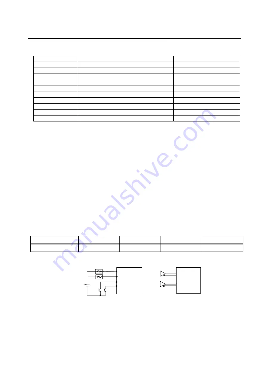
3.2.3 Position command pulse input signal
To use the drive in position MPG mode, input the position command pulse by using the open
collector input, line drive input, and pulse output of the MPG (Manual Pulse Generator) or PLC
position control card using external power supply of 5 [V] and 24 [V]. The types of pulses that can
be used are "dir pulse", "forward pulse + reverse pulse", and "LEAD pulse + LAG pulse".
Select the type of pulse from the Pulse Logic (P4-04) menu of the front operation panel Position
Mode (P4--) menu
Photo-coupler has been used in the pulse input circuit to insulate the internal control unit of the drive
system from the external pulse signal. However, if 5 [V] is used as the open collector input, connect
1/2W 150
Ω
resistance, or 1/2W 1.5k
Ω
resistance if 24 [V] is used.
Pin No ( CN1- )
PPRIN ( 9 )
PRIN ( 12 )
PPFIN ( 11 )
PFIN ( 10 )
Signal function
+ 5VA
R pulse input
+ 5VA
F pulse input
PRIN
Driver
PFIN
[Position command pulse application circuit(example)]
PPFIN
5V
(24V)
*(Caution!)connect 1/2W 1.5kΩ if 24V power is used
PPRIN
* In case of open collector input
PPFIN
PFIN
PPRIN
PRIN
* In case of line driver input
Driver
(SN75174)


