


Chapter 3. Wiring and Signals
3-9
3.2 Connection and signal-form of input/output
3.2.1 Input contact signal
Function of each input contact signal is shown on the following
table. The input contacts are classified into A contact and B
contact depending on the contact characteristics. Check before
use. Connect external power supply greater than DC +24 [V], 1 [A]
to the +24 [V] power input terminal (CN1-49) to use the contact
input.
Pin number (No.)
Signal function in controlling
position
Contact Type
COMSEL0 (18)
Position Command selection 0
COMSEL1 (43)
Position Command selection 1
COMSEL2/CCWJOG (17)
Position Command selection 2
/CCWJOG
COMSEL3/CWJOG (42)
Position Command selection 3
/CWJOG
COMSEL4/MPGEN (16)
Position Command selection
4/MPGEN
ON=1, OFF=0
Select thirty two position CMD
In the case of MPG_SEL(P8-
06)=1,
MPGEN signal : ON => Pulse
command operation
In the case of P8-03=2, CCWJOG/
CWJOG operation(17,42)
START (41)
Start Command
ON = Starting operation
SVONEN (15)
Enable to servo operation
ON = Servo drive enable
CCWLIM/JOG (40)
Not CW/ CW Jog
OFF = Not CW/CW Jog
CWLIM/JOG (14)
Not CCW/ CCW Jog
OFF = Not CCW/CCW Jog
ORG-DOG/ORG-RET (39)
Origin DOG switch
If P8-07=0 & ON, Dog switch range
If P8-07=1 & ON, Origin Return
ORGCOM (13)
Origin Command
ON = Origin operation
ALMRST.STOP (38)
ALARM RESET/ Motor stop
ON = ALARM REST
ON = Motor stop
Note 1)
ON : Application contact connected to “ GND24”
OFF : Application contact connected to “+24V”, or applicable contact not connected.
Note 2)
ALARM RESET do necessarily after servo drive ENABLE(SVOEN) signal OFF.
Note 3)
If we select CW/CCW Jog function(P8-03:LIM_SEL:1), cannot use CW disable/CCW
disable function.
Note 4)
If we select CW/CCW Jog function(P8-03:LIM_SEL:2), can simultaneously use both CW
disable/CCW disable function and CCWJOG(17)/CWJOG(42) function.
3.2.2 Output contact signal
The output contact signal functions are shown on the
following table. The output contact internally uses transistor
switch. Take precaution because overvoltage or overcurrent
may cause damage to the system. (Power supply: DC +24 [V]
±
10%). Brake signal is used to drive the brake installed
inside the motor. The sequence must be configured so when
this output is turned on, power is supplied to the brake and the break is released. Other signals are
the outputs which indicate the status of the drive system and the motor. Each function is shown on
the following table.
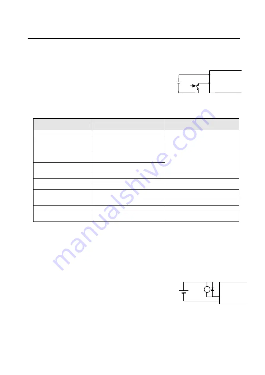
Driver
Input contactor wiring(example)
+24VIN
Speed1
+24V
ON
구동장치
출력접점 배선방법(예)
GND24
BRAKE
24[V]
M1
Output contactor wiring(example)
Drive
(note) M1 is external relay for the brake.


