


HD Link Installation & Operation Manual
4 – Front Panel Configuration & Operation
Version 2, April 2010
4-4
Harris Corporation
Intraplex Products
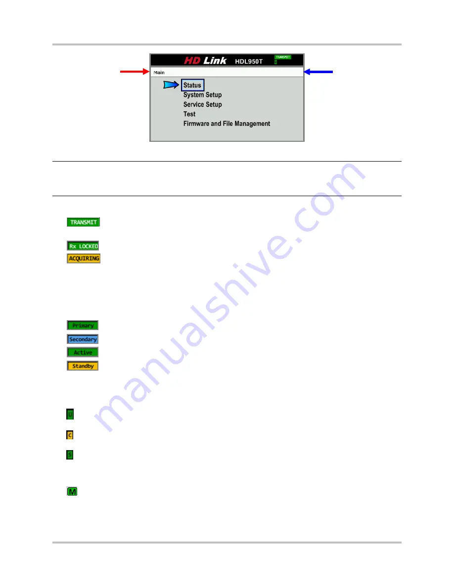
Figure 4-3. Main Front Panel Screen
Note:
A
navigation record bar
appears at the top of all front panel display screens except the original
default screen. (Red arrows point to the bar in ongoing screen examples.) Use this bar to
remember previous screens and understand where you are as you drill down for more
information or to edit parameters.
You can check the system status in the upper right of each screen:
●
= Transmitter in Operate mode
●
Transmitter in Standby mode = no message
●
= Receiver in Operate mode when transmitter is in Operate mode
●
= Receiver in Operate mode when not receiving adequate transmitted signal
●
Receiver in Standby mode = no message
For this status, green indicates no error and yellow indicates an alert. Screens of a transmitter in
Operate mode appear most in this section, but some combination of the other modes for transmitter
and receiver appear as well.
You can check any redundancy status in the upper left of each receiver screen:
●
= Receiver in Primary mode
●
= Receiver in Secondary mode
●
= Receiver in Active mode, receiving transmitted signals
●
= Receiver in Standby mode, ready to receive signals upon switchover
Transmitters should not show the Primary/Secondary and Active/Standby indicators, since they should
both be set to Standalone to work with a Main/Alt controller.
Single letters sometimes appear below the status messages:
●
= A green USB Device status letter appears if a USB device is plugged into the front panel’s
USB slot and the device can be read by the HD Link unit.
●
= A yellow Calibration status letter appears if the unit has not been calibrated. If the C does not
appear, the unit has been calibrated.
●
= A green Service Sync status letter appears when this function is operating on the receiver.
You cannot make configuration changes when the service sync is on. To make any configuration
changes, go to
Service Setup
Service Sync
on the receiver to turn off the sync function
(Section 4.1.6.4).
●
= On the main
Status
screen, a
green
Mirroring Port status letter appears if an Ethernet cable
is plugged in and connected to another device with the Ethernet link up, as one port is mirroring
the other one. The M is
red
if the mirror port is not connected to anything or the other device is
not up.
Navigation
record bar
System Status