


HD Link Installation & Operation Manual
5 – Web Browser Interface Configuration & Operation
Version 2, April 2010
5-14
Harris Corporation
Intraplex Products
9.
To use a test tone when testing audio transmissions, select the
Turn on test tone
check box
(transmitter only).
10.
Move the
Input Level
(transmitter) or
Output Level
(receiver) slider to the right or left to set
the audio output/input full scale value (possible range is +9 to +24 dBu). The numeric level to the
right corresponds to the level set on the slider.
11.
Click
Save Configuration
to
record your changes
.
12.
Click
Reset
to revert to previous configurations
without saving your changes
.
13.
Click
Close
or
to exit the dialog box.
14.
Click
Submit Configuration
on the
Program Services
page to
apply your changes
.
5.3.4.3 Auxiliary Port Configuration Procedure
1.
At
Configuration
, click
. The
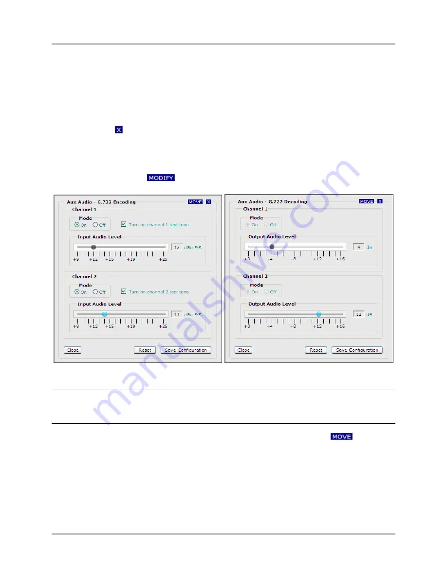
Audio 1/2 Configuration – G.722 Encoding/Decoding
dialog box appears (Figure 5-11).
Figure 5-11. Aux Audio G.722 Encoding/Decoding Config Dialog Box –
Transmitter and Receiver
Note:
On the receiver interface, if you click
Modify
and the dialog box appears with most of the
parameters inaccessible, the Automatic Configuration function is enabled (Section 5.3.6.2).
You must clear the
Automatic Configuration
check box on the
Advanced Settings
page
before making changes to the audio configuration.
2.
To change the location of the dialog box on your monitor screen, click and hold
and drag
the dialog box as desired.
3.
At
Channel 1
, select the
Mode
:
•
On
•
Off
4.
To use a test tone when testing audio transmissions, select the
Turn on channel 1 test tone
check box (transmitter only).
5.
Move the
Input Audio Level
(transmitter) or
Output Audio Level
(receiver) slider to the right
or left to set the audio output/input full scale value (possible range is +9 to +25 dBu for input or