Section 4
♦
Operating the CMN-41
56
CMN-41 Series Installation and Operation Handbook
Copyright © 2009, Harris Corporation
A GPI output dry-contact closure can be used to alert other devices when an alarm
occurs. Use the Unit Configuration
→
GPIO selection option (page 71) to set up the
GPI.
Alarm Status Display
The Alarm Status screen lists all the alarms, the state of each alarm setting, the current
alarm limit selection (if applicable), the current alarm duration (if applicable), and the
Accumulated alarm column.
The Alarm Status display is accessed via the Alarm Setup menu. Press and hold the
ALRM function button to access the Alarm Setup menu. Use the Up/Down navigation
buttons to scroll to the Alarm Status selection option. Press the ENT navigation button
to select the Alarm Status display.
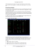
An alarm status display diagram is shown in
Figure 4-35
. The diagram illustrates the
general location for the various alarm status display fields.
Figure 4-35. Alarm Status Display Diagram
The alarm status screen contains detailed information concerning alarm status
indicators. This information is separated into columns sorted by alarm name, whether
or not the alarm is enabled, lower and upper limits, thresholds, duration, and total
number of alarms. The alarm name text can appear in a colored state. The colored
states are:
•
White
: indicates alarm is not enabled.
•
Green
: indicates alarm is enabled and not exceeding alarm limits.
•
Red
: indicates the alarm is enabled and exceeding an alarm limits.

