CMN-41 Series Installation and Operation Handbook
25
Copyright © 2009, Harris Corporation
Section 4
♦
Operating the CMN-41
Overview
In the CMN-41, certain buttons function differently, depending on the parameters
selected. Once the function is determined, more detailed settings can be configured.
This section focuses on the operation of the CMN-41 according to the selected display.
See
Figure 3-1
on page 16 for information about the location of the buttons described
in this section. See Section 3 for general information on how the CMN-41 operates.
Waveform Display
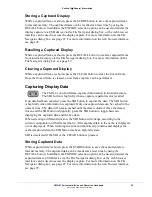
Press and release the WFM function button to access the Waveform
display. The waveform graticule scales, units of measure, and critical
amplitude limits change according to the video format displayed.
Press and hold the WFM function button to access the Waveform Setup menu selection
options. (Press the SETUP or the EXIT button to clear the Waveform Setup menu.)
Table 4-1
shows the Units of Measure that appear for a video format.
Table 4-2
lists
the
critical amplitude limits, which are indicated on the screen by special dashed lines
for the video formats that can be displayed.
Table 4-1. Video Formats and Units of Measure
Video Format
Unit of Measure
High Definition and Standard Definition 525 and
625
Volts or Percent (Selectable)
High Definition 59.94 or 60, or Standard Definition
525 displayed as composite (NTSC)
IRE
High Definition 50 or Standard Definition 625
displayed as composite (PAL)
Units or Volts (Selectable)
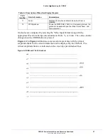
Table 4-2. Video Formats and Critical Amplitude Limits
Video Format
Critical Amplitude Limits
High Definition and Standard Definition
0.6125 V = upper 75% chroma limit
0.525 V = 75% luminance limit
0.350 V = 50% point; black for color difference
channels
0.0875 V = lower 75% chroma limit
Standard Definition 525 as Composite (NTSC)
7.5 IRE – black level
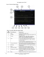
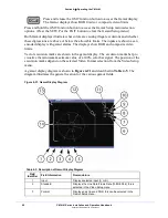
A waveform display is shown in
Figure 4-1
and described in
Table 4-3
. The figure
shows the location for the various waveform display fields.


