Documentation HG G-73650ZD | English, Revision 05 | Date: 09.03.2017 | www.goetting-agv.com
10
Chapter 2: Basic Principles of Track Guidance
2.2 System Composition
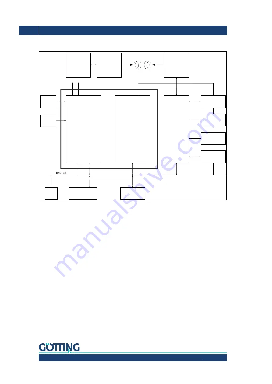
Figure 3
Block diagram system structure
Due to the strict separation of the track controller, sensor fusion and navigation system and
the smart interaction with the vehicle control, the navigation controller offers a high degree
of flexibility and is also suitable for monitoring safety-critical vehicle components.
2.3 Position Determination with Sensor Fusion
The sensor fusion calculates the current position and the vehicle's orientation. The sensor
fusion provides the steering controller with the following data set (also referred to as
pose
):
–
X Position
–
Y Position
–
Speed
–
Vehicle orientation
If the internal sensor fusion is used, the position of the vehicle is calculated from the odom-
etry, initialized and corrected by the transponder antenna and/or the GPS system. The tran-
sponder antennas will then be connected via CAN bus. Additionally their posi pulse has to
be connected with IO-3 (see manual of the antenna). The optional Gyro is connected via
CAN bus as well and is intended to enhance the odometry.
IO 1-3
A/B
A/B
Navigation Controller
Incremental
Encoder
(optional)
Incremental
Encoder
(optional)
Hardware Control Unit HG 61430
Gyro
HG 84300
(optional)
Transponder-Antenna
HG 98810 / HG 98820 /
HG 98850
(up to 4, optional)
GPS Antennas 1 & 2 (optional)
Track
Guidance
Controller
Vehicle PLC
Internal
Sensor fusion
Transponder
and/or GPS
IO 4
Central
Control
Unit
Narrow-band
RF Modem
(optional)
Narrow-band
RF Modem
(optional)
Steering Servo
Acceleration
(optional)
Break (optional)
Emergency Stop
(optional)
External
Sensor Fusion
e.g. Laser Scanner
(optional)


