G-Force® & Easy Arm Q2 - iQ2 Service Manual
Gorbel Inc.
Revised 5/21
9 - 31
Removal and Replacement Procedures
SLIDING HANDLE
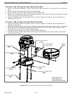
Procedure S-1A. Swivel Sub-Assembly Removal:
Note: This procedure assumes the Coil Cord and Wire Rope assemblies have been removed prior to performing
any repairs on the Sliding Handle itself. Refer to the system installation procedures in Chapter 3 for speci
fi
c instruc-
tions regarding Coil Cord and Wire Rope removal.
1. Remove the M16 custom hex head cap screw (HHCS) and M16 Belleville washer from the top of the swivel
assembly. Note the orientation of the Belleville washer, concave side down
2. Slide the swivel assembly o
ff
the top of the handle shaft, noting location of electrical connector.
Note
: Set aside
the swivel sub-assembly with the PCBs facing upward to avoid damaging them.
Procedure S-1B. Swivel Sub-Assembly Replacement:
1. Slide the swivel assembly onto the top of the handle shaft, ensure PCB tabs align to the slots in the cast Hous-
ing Sub-Assembly.
2. Install the M16 custom hex head cap screw (HHCS) and M16 Belleville washer (concave side down) onto the
top of the handle shaft.
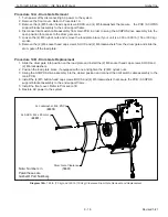
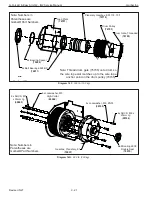
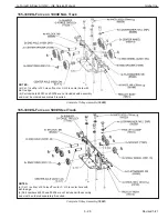
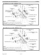
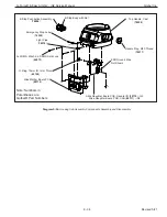
Diagram S-1
.
In-Line Slide Handle Swivel Sub-Assembly Removal and Replacement.
Flatwasher, M16, ZNPL
(
01310
)
Lockwasher, M16, ZNPL
(
00212
)
Note: Numbers in
Parentheses are
Gorbel® Part Numbers
Hexnut, M16, ZNPL
(
65063
)
Hook Latch Assembly
(
74199
)
Hardware Kit
(
74251
)
(see inset)
Swivel Sub-Assembly
(
74249
)
Housing Sub-Assembly
Air Extension O-Ring
(
65104
)
Air Extension Output, DN8 (1/4 NPT) (option)
(
74240
)
Linear Transducer Sub-Assembly
(
74246
)
Grip & Shaft Sub-Assembly
(
74245
)
HHCS, M16 x 2mm Pitch
with Channel
(
74281
)
External Snap Ring, 25.4mm
(
65069
)
Belleville Washer, M16
(
65098
)
2x Collector O-Ring
(
74269
)


