G-Force® & Easy Arm Q2 - iQ2 Service Manual
Gorbel Inc.
Revised 5/21
9 - 45
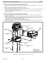
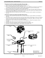
Procedure P-6A. Plunger Assembly Removal
1. Remove either side guard. Refer to Procedure P-1A.
2. Remove both levers and the lever shaft. Refer to Procedure P-2A.
3. Remove the M4 button head cap screw (BHCS) and M4 large OD washer.
4. Slide both plunger assemblies out of pendant handle housing.
5. Remove the plunger springs from plunger assemblies.
6. Remove the plunger tips from plunger assemblies.
Procedure P-6B. Plunger Assembly Replacement
1. Install the plunger tips into the plunger assemblies.
2. Install the plunger springs into the pendant handle housing.
3. Install both plunger assemblies into the pendant handle housing.
4. Install the M4 button head cap screw (BHCS) and M4 large OD washer to secure the plunger assemblies in the
pendant handle housing.
5. Install both levers and the lever shaft. Refer to Procedure P-2B.
6. Install the side guard. Refer to Procedure P-1B.
Diagram P-6. Plunger Assembly Removal and Replacement.
2x Plunger Assembly
(
74323
)
2x Plunger Spring
(
89015
)
2x Plunger Tip
(
74321
)
Apply Blue Loctite 242
BHCS, M4 x 8mm Lg
(
65077
)
Note: Numbers in
Parentheses are
Gorbel® Part Numbers


