


G-Force® & Easy Arm Q2 - iQ2 Service Manual
Gorbel Inc.
Revised 5/21
9 - 33
Procedure S-3A. Housing Sub-Assembly Disassembly
1. Remove the swivel sub-assembly or remote mount cap sub-assembly. Refer to Procedure S-1A or S-2A accord-
ingly.
2. Remove the housing sub-assembly. Refer to Procedure S-3A.
3. Remove (4) M5 socket head cap screws (SHCS) and M5
fl
atwashers.
4. Separate the handle top sub-assembly from the handle bottom. Use caution, the ribbon cable, Operator Present
Sensor, and ground wire will still be connected.
5. All the sub-assembly internal components can be removed or replaced if necessary; use the exploded view
drawings as a reference.
Procedure S-3B. Housing Sub-Assembly Reassembly
1. All the sub-assembly internal components can be removed or replaced if necessary; use the exploded view
drawings as a reference.
2. Once all the internal components have been positioned properly, slide the handle bumper in place on the handle
bottom and join the handle top sub-assembly with the handle bottom. Make sure the ribbon cable, Operator
Present Sensor, and ground wire are connected properly.
3. Install the (4) M5 socket head cap screws (SHCS) and M5
fl
atwashers.
4. Install the housing sub-assembly and swivel or remote cap sub-assemblies as required. Refer to Procedures
S-3B and S-1B or S-2B.
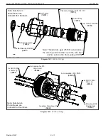
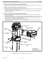
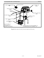
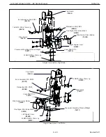
Diagram S-3a
.
Housing Sub-Assembly Assembly and Disassembly.
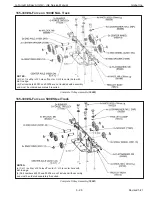
Operator Present Sensor
(
78615
)
NOTE LOCATION OF
NUT AND WASHER
Bumper
(
74207
)
LCD Window
(
74223
)
2x External Snap Ring, 6mm
(
65065
)
Sliding Handle Bottom
(
74209
)
4x Lockwasher, M5, High-Collar
(
65062
)
2x Handle Pushbutton
(
74215
)
4x SHCS, M5x0.8-55
(
65067
)
Note: Numbers in
Parentheses are
Gorbel® Part Numbers


